Three different drive mechanisms
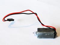
The toy doesn't need much power to move, but it needed a transmission to adapt the speed of the motor to the speed of the wheels. Furthermore, the drive mechanism should give way if someone chooses to play with the toy in an old-school fashion, pushing it around on the floor.
The motor I scavenged from a CD-ROM drive is just on the edge of being too weak. On the other hand, it is suitably small for the limited space under the battery compartment.
First try: Worm-gear
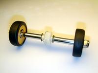
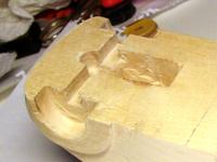
In the CD-ROM drive the motor drove the seek mechanism through a worm gear. It gives a good gear ratio and definitely enough torque, but aligning the gears accurately turned out to be quite difficult. Limited space forced me to put the motor at an angle, but wood is difficult to carve precisely when not working along the grain. In addition to this vertical alignment, I also had problems with horizontal positioning.
Had I permanently glued the gear to the back axis, the car would obviously go "klik klik klik" when pushed, breaking the transmission in progress. But a simple tight fit was not enough either, because the twisted teeth of a worm gear would push it to one side, until it would no longer mesh with the worm. I positioned the gear in correct place with an arrangement of two circlips and some superglue for proper friction between the gear and the axis.
Even with these solutions, however, the combined horizontal movement of the axis in bearings and the vertical flex in the worm caused it to often lose contact. The teeth of the gear were only 1 mm deep after all, so I wanted to find a more toy-proof approach.
Second try: Belt drive
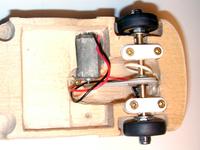
Belt drive was actually my first idea, but it had its own problems because of the size of the rear wheel. To achieve high enough gear ratio the belt wheel in the back had to be almost as large as the back wheel itself, causing a really small ride height.
My experiment with a single belt drive was very promising though: it was realiable, gave almost enough torque and definitely easier to set up than the gear drive. Whereas the gears required tolerances of less than 1 mm, the belt let me adjust the motor position by 2 cm so that it would fit nicely with the other parts.
The belt wheels are made of polycarbonate. They are very easy to make by sawing an octagon, putting it on a bolt and turning on Dremel while shaping with a file or blade.
Solution: Two-belt drive
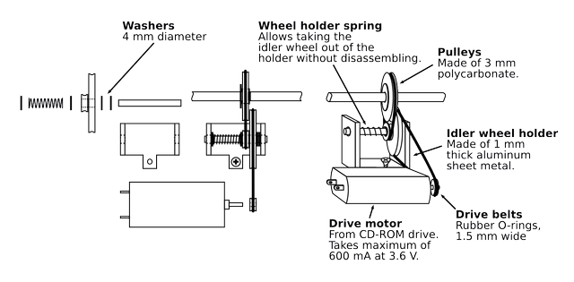
The final solution was an obvious step forward from the single-belt drive. I made an U-shaped holder of aluminum plate and added an idler wheel to increase the gear ratio. This also allowed me to reduce the size of the rear wheel.
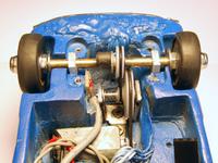
The only remaining problem was finding suitable belts. I had some from a LEGO set, but they broke during all the testing and careless assembly. I tried some made of balloon inlet rings; better than nothing, but really uneven quality. I had thought about using rubber O-rings that are used for sealing pipes and valves, but had some doubts about their flexibility.
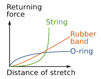
Anyway, I bought some O-rings for testing. It turns out that they actually don't flex like rubber bands. However, their force-distance relation was even better for belt use than what rubber bands have.
I'll elaborate on that: normal springs and rubber bands obey the Hooke's law, which says that the returning force is proportional to the scretch distance. I expected that the O-rings might behave more like a string: not flexing much, but instead snapping when the force is too great. Instead the O-rings seem to have almost constant returning force over a large range of flex. Atleast this is what I gathered by stretching them with my fingers, so don't assume that the picture on the left is accurate to any degree.
The constant force is good for belt use because you can stretch the belt to whatever length is necessary, and the returning force won't grow too large and overload the sleeve bearings.
Other stuff on the back axis
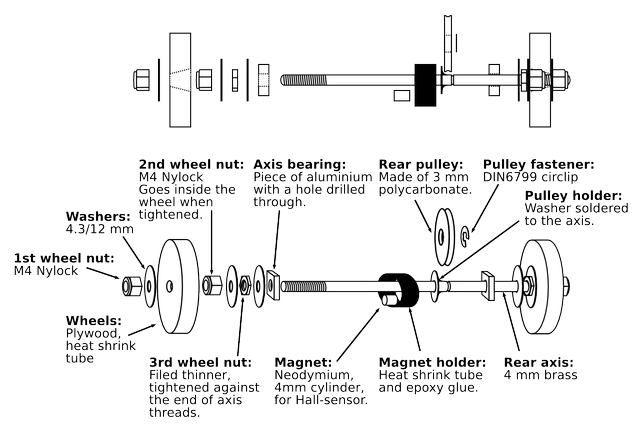
The back axis also has a Hall sensor to detect whether the wheels spin. It is a fall back sensor in case the optical sensor fails to detect an obstacle, for example if the object is black and does not reflect light. The Hall sensor is from a floppy drive, takes 3.3 volts in and gives open-collector digital output.
Bearings on the back axis are just simple aluminum blocks with a hole through them. I first tried to use pieces of FM radio antenna pipe as sleeve bearings, but they didn't slide well enough. Bearings on the back axis are not very important as long as the motor is strong enough to spin the wheels.
Drawbacks
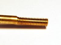
Wobble wobble.. the thread on the back axis is crooked and the wheels therefore a bit eccentric. It is surprisingly difficult to get the threads go straight for even just 2 cm. But in a toy like this, it only makes it cuter.
Like many toys, also this car suffers from hair collecting around the axis. Fortunately the large 4 mm axis makes it a lot easier to remove the dirt than some 2 mm rods seen in commercial toys. I don't know any solution to this problem, except making the ride height large enough to not touch the hair on floor or carpet. Or just keep your floors clean!
– Petteri Aimonen on 3.8.2010

