
Software logic
There is strange thing about software in embedded systems: it is always the easy thing until you actually have to start writing it. This time it was a lot easier than usual, because of two reasons: 1) I used C instead of ASM, even though PIC is not very well suited for it, and 2) I was able to make hardware modifications after starting with the software.
The PIC16F689 processor has 4096 words of program memory and 256 bytes of RAM. My program uses 3094 code words and 166 bytes of RAM, with 666 lines of code (comments and blank lines are not included in count). I used SDCC as my compiler, and I am quite satisfied with it. Sure the generated assembler is a bit bloat and it has a few bugs, too, but it gets the job done. Could also improve the code size easily, but I didn't bother because it fit without even looking at the assembler.
Inputs and outputs
To clear things up, here is a drawing of all the inputs and outputs in the car:
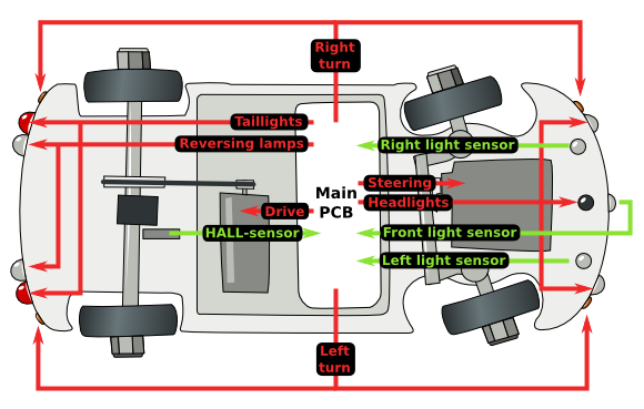
The car has four sensors: one phototransistor in front for obstacle detection, two underneath for path/floor detection and one Hall-sensor near the back axis to detect jams. Phototransistors are connected through analog-digital converter, whereas the Hall-sensor has a digital output.
Outputs are the 5 sets of LEDs, and the outputs to servo and the motor.
Basic software structure
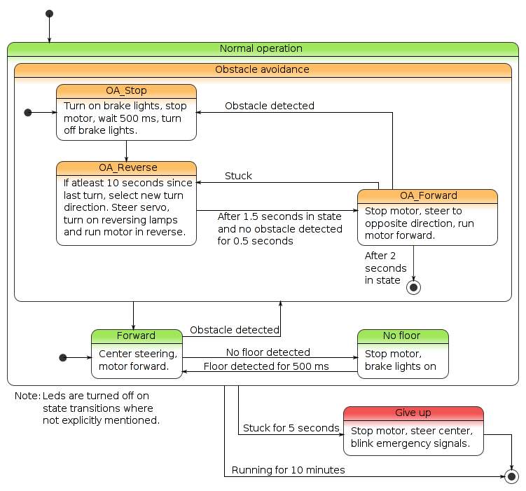 State diagram of the car control logic.
The logic of the car is a state machine that runs in the main loop of the program. An interrupt routine provides necessary abstraction to this state machine, such as generating the control pulses to servo and reading the ADC.
Originally I intended to make the logic a lot more complex, so that the car would follow paths and also detect whether it is following a path or a line. Some problem in the bottom sensors crushed these plans. However now that it is done I think it makes a better toy for the target audience with this simpler logic.
Interrupt routine
The interrupt routine triggers on TMR1 overflows. The code contains a trivial scheduler that decides the time of the next interrupt based on requested events, such as "next ADC measurement in 1 ms" or "servo pulse ends in 1520 µs".
Getting accurate enough pulses for the servo was a small problem. Adding some tolerance in the timings helped, so that if another event was pending in the next ~50 microseconds, it would get executed in the same interrupt. Otherwise it would have to wait until everything else in that interrupt was executed, which could take over 100 microseconds. This still wasn't good enough, so I just raised the clock frequency from 4 MHz to 8 MHz to make everything run more smoothly.
Modulated light detection
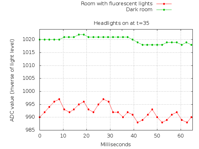 Light sensor waveforms from measurements.
The interrupt routine continuously toggles the headlights on and off and performs ADC measurements before each toggle. The measured values are subtracted, and the larger the value the more reflected light was detected.
Or that was the simple version. Actually there is a lot other noise in the light readings, such as moving shadows and 100 Hz (2x50 Hz) pulses from lamps. I solved this by averaging the values over multiple toggles for a period of 70ms. This period is divisible by 10 ms, eliminating the 100 Hz noise, and the averaging solves most other noise problems.
The resulting value is clean enough so that I can trigger steering as soon as one 70 ms measurement cycle gives a positive result.
Further development
The car might work as a basic robotics development system, assuming it first survives several years of playing. The interrupt service simplifies the hardware details, so that coding the software in C is relatively simple. I guess the Lego Mindstorms is simpler though..
The source code is available here.
– Petteri Aimonen on 6.9.2010