Control electronics
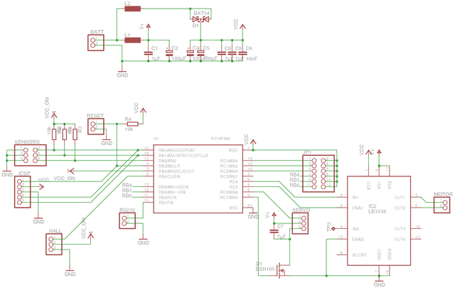
I'm starting to get a bit fond of the PIC16F689 microcontroller; it is small enough, has internal oscillator and good enough peripherals. Another nice chip I used for the car electronics is LB1838 motor controller from an old floppy drive. It has two integrated H-bridges and logic level control signals.
Power management
The car does not have a real power switch, but instead relies on soft power-off under software control. Therefore all parts have to either have a sleep mode (PIC, LB1838) or have switchable power (sensors, servo). Switching the servo power off also allows about saving about 10 mA of current when the car is not turning.
The power button is connected to microcontroller reset pin. Therefore it can wake up the microprocessor without any interrupts enabled. I usually connect the power button to reset instead of interrupt, so that even if the software crashes the power button still works.
The servo causes quite much noise on its power line, which could disturb the analog signals from sensors. I have separated the high-power V+ supply from the logic supply Vcc with a diode and separate filtering, so that any high-current spikes on V+ won't cause Vcc to drop. Having the LEDs on Vcc network was a compromise in PCB layout and probably a bad choice, because they load the Vcc supply quite a lot.
Sensor signals are not too sensitive to interference, though, because they are connected in a voltage divider configuration between Vcc and GND. The microcontroller ADC uses Vcc as reference voltage, and therefore the results are unaffected by changes in Vcc voltage.
Sensors
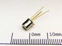
Despite the availability of sensors like IS471F, I chose to use simple phototransistors of type BPW14N. Part of the idea was that the car could also be programmed for e.g. phototropic behaviour instead of the obstacle detection.
I assumed that the 10 bit ADC converter would be enough to detect the modulated reflection in software, and it almost was. However because I already had made the PCB I had to figure how to increase the sensitivity. Simply increasing the value of the pull-up resistor would help, but then it would get saturated in bright light. I needed a high-pass circuit to separate the modulated signal from background illumination.
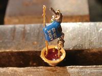
RC-circuit is the simplest high-pass circuit one can build. After some careful thought I realized I could simply connect a parallel RC-circuit in series with the sensor and then increase the pull-up resistance to 100 kΩ. With 100 nF capacitor and 100 kΩ resistance the filter has a corner frequency of 16 Hz. Because DC current divides between the two 100 kΩ resistors and AC current between the 100 kΩ pull-up and the capacitor, the sensor has about 2 times higher sensitivity for the 500 Hz modulated light.
Circuit board

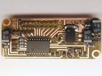
I etched the circuit board myself. All the traces are on one side; the other side is a solid ground plane with small circles drilled out around pins to prevent short circuits. The ground plane was easy to make because it needed no etching or alignment, and it made routing easier and may also improve EMC performance.
I didn't take the height of the connectors into account, so I ended up having to bend some of the pins to make the connectors fit under the battery holder.
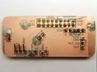
The annotations on the board are on a transparent sticker. It is a lot easier to get connectors in right places this way :) I also tried to iron on the silkscreen, but it didn't stick for some reason (maybe the board was not dry enough?). By the way, I noticed that the catalogs from Maxim IC have a coating that makes white traces when heat-transferred — this could be really cool for making markings on a black box.
In case you want them, here are the Eagle design files:
– Petteri Aimonen on 4.8.2010

