
Comments for “Electrical connections”
Just burned my other panel :/

It got left in a garbage state where VDD was low but some IO pins were high => about 100mA flowing through ESD diodes in the panel drivers => IO pins burned.

To avoid this, better only drive the panel VDD to "1" or "Z", never "0".
— Petteri Aimonen on 07.12.2013 at 13:13 (UTC)
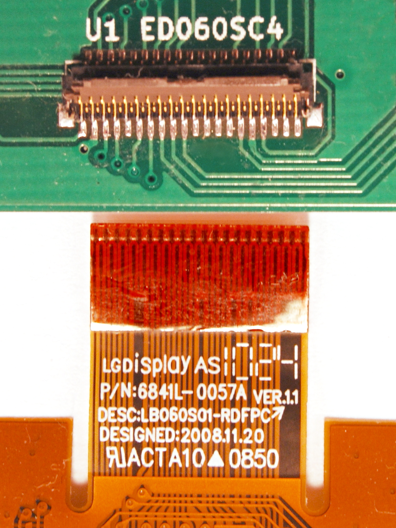
Looks like half of the unexplainable signals (like SHR or U2CE1) are actually not connected to the display at all:
http://koti.kapsi.fi/jpa/stuff/pix/eink_connector.jpg

Simplifies routing a bit :)
— Petteri Aimonen on 18.01.2014 at 15:45 (UTC)
Can I adapt your schematic to use it for a ED050SC3 (wich is very similiar)? I did some digging and I believe its posible. Can you quickly look at: http://datasheet.eeworld.com.cn/pdf/AZDISPLAYS/285043_ED050SC3.pdf for example and tell me if it looks almost identical? I believe I can build something like your project and take a spin with it :D By the way, great article, sad to hear it kinda died.
— Nico on 15.04.2014 at 10:11 (UTC)
FYI, The paragraph states 3.3v for VSS but the schematic and eink datasheet show it to ground.
— Alex on 05.06.2014 at 04:23 (UTC)
@Alex

It means that 3.3V goes between Vdd and Vss.
— Petteri Aimonen on 05.06.2014 at 04:34 (UTC)
I have ED060ST1 (LF) - it's a first e-ink display.
Can I adapt your schematic for it?
— Alex on 27.06.2014 at 19:45 (UTC)
@Alex

Should work, you just have to find the datasheet with the pinout somewhere.
— Petteri Aimonen on 28.06.2014 at 07:38 (UTC)
There are no the datasheet for ED060ST1(LF) anywhere. This is a problem.
But thank you!
— Alex on 29.06.2014 at 06:13 (UTC)
I went to examine the connector my self and found all of them to be separate. http://threadedthinking.com/eink/connector.jpg I wonder how many versions of the ED060SC4 are there. It sounds like there is a v2 but I do not know how to differentiate it.
— AlexR on 06.07.2014 at 02:37 (UTC)
So (thanks to sprite_tm for research) it turns out that the display I've been using is a LB060S01-RD02, which is a clone of the ED060SC4-V2.

Seems that the clone does not have all the pins connected, while the real one does. It also seems that there is some trouble with driving the real thing, sprite_tm is trying to figure that out.
— Petteri Aimonen on 12.07.2014 at 06:36 (UTC)
Interesting, I have put together a new board, power supply and screen and still no luck. I will try to order one of these clones to see how it goes. It looks like the vcom voltage sticker is right above the decoupling caps on thes LG boards.
— AlexR on 16.07.2014 at 04:42 (UTC)
Yeap, works great with an LG board, primeview is a bit off. looking at the datasheet of the LG, it looks like VEE should be connected to another pin as well.
— AlexR on 17.07.2014 at 21:18 (UTC)
Hi,
have you measured or tested the LT3463 output characteristic u(i)? I have used LT1945 (much cheaper). It should also be a little stronger: 350mA switch-current-limit per LT1945, instead of 250mA with your LT3463. My converter behaves strange, doesn't regulate voltage well, it is dropping fast with the load current. At 30mA it drops about 2.4V, crazy... I suspect your LT3463 might give even weaker output, with the smaller current limit.
Have you measured the voltage stability, accros load current?
Thanks, Jan
— Jan on 28.01.2015 at 17:19 (UTC)
@Jan

No, I didn't measure it very much. I did take a look at the ripples when it was operating - IIRC they were around 500mV in the >20V supplies and very small in the regulated 15V supplies.

Another voltage regulator chip worth a look is MAX17135, which is designed specifically for E-Ink drivers.
— Petteri Aimonen on 28.01.2015 at 18:02 (UTC)
My LT1945 has 120mVpp ripple at 30mA. (positive output measured yet only).
Can you please measure for me the voltage drop at 10, 20, 30mA or so, to compare? I am trying to figure out the error. I don't know if the weak output is normal or not.
Thanks a lot
Jan
— Jan on 28.01.2015 at 19:53 (UTC)
@Jan

I no longer have the board with me (it went into a device I gave as a gift). So cannot make measurements.
But 120mV ripple in those voltages shouldn't matter much for the display.
— Petteri Aimonen on 30.01.2015 at 18:24 (UTC)
Hi Petteri,
Is it possible to convert these kicad schematics and library to Altium designer? Unfortunately, I have no previous experience with kicad and all Altium sees is an empty sheet.
Regards and thanks for the amazing tutorial,
Onur
— Onur on 05.02.2015 at 12:02 (UTC)
the datasheet says
6-1) Panel interface description
This panel is driven by ASIC PVI-6001A or “Apollo” display controller ASIC.

i am a little confuse about the controller do i sill need  S1D13521 to drive the screen ,

is this possible please that you could be able to explain this controller thing a little
— gaurav on 06.02.2015 at 12:52 (UTC)
sir i am also going to drive it directly with a mcu or with a linux machine.

can you please explain what this PVI-6001A thing is?
— gaurav on 06.02.2015 at 13:34 (UTC)
Okay, I have the ED060SC4 working too. Complete writeup is at http://spritesmods.com/?art=einkdisplay , but the short of it is that the display has CE2/CE3 signals that aren't in the datasheet but need connecting too. The timings I use also are reverse engineered from a working E-ink reader, so that may be a factor too.
— Sprite_tm on 16.02.2015 at 18:37 (UTC)
Hello again,
What should be used as D1 diode? Also its symbol looks like a zener, is D1 a zener diode? If so what's its zener voltage and opening voltage?
— Onur on 21.02.2015 at 09:00 (UTC)
Also, are there any resistors or capacitors that need high power or voltage rating? What should be the minimum I should use?
Thanks a lot
— Onur on 21.02.2015 at 09:13 (UTC)
Here is the list of Farnell numbers for most of the parts:
http://koti.kapsi.fi/jpa/stuff/other/eink_example_parts.txt

You can find more information about needed voltage ratings in the SMPS controller datasheet. If I remember correctly, C2 needs 50V or so and the rest are quite predictable.
— Petteri Aimonen on 21.02.2015 at 10:18 (UTC)
Hi folks

is there Altium library for this connector 939pin 0.300 pitch)??? (or other software that might have it)
Or where I could get one, wanna build my PCB but this thing is keeping me from it
Any help would be great, Thanks
— Dario Budimir on 16.07.2015 at 09:47 (UTC)
@Dario The datasheet should have enough information to create the component yourself. I did the same myself in KiCAD.
— Petteri Aimonen on 16.07.2015 at 13:26 (UTC)
hello  all,
i have ED060sc4(LF)  display , in datasheet 7 pins  are NC , but  in my display all pins are connected, as i think  here  is CE3  pin  too,  but  i  can't  find ED060sc4(LF) datasheet , could  anyone help me?


thanks
— giorgi877 on 10.08.2015 at 13:23 (UTC)
Hi Petteri! Can you sell on ebay your PCB driver board based on stm32L151?
— MIkhail on 01.11.2015 at 05:20 (UTC)
@Mikhail No, currently I don't have these boards available for sale.
— Petteri Aimonen on 01.11.2015 at 09:17 (UTC)
Hi Petteri,

will you be able to share your code privately? I designed a custom PCB but have yet to get the display to toggle between white and black for testing.

Thanks and blessed new year!
— Kenneth on 28.12.2015 at 14:29 (UTC)
All that I have is already publicly available. https://svn.kapsi.fi/jpa/uunimittari/receiver_sw/ is one eink project that I have been too lazy to write about.

But it seems that displays may vary a bit in their functionality, especially the GMODE etc. pins. Sprite_tm's blog has some good info, and at some point you may just have to do it by trial & error.
— Petteri Aimonen on 28.12.2015 at 16:49 (UTC)
Hi Petteri,

You have a photo on the first page, the one with the E-ink connector and on board FPC connector. My question, do you remember from which side is the connector PIN 1? From LEFT side or RIGHT side. I ask you this because The documentation is a bit ambiguous.

Thanks!
— Marius on 13.05.2016 at 14:26 (UTC)
The datasheet page 5 has markings for pins 1 and 39: http://essentialscrap.com/eink/ED060SC4V2.pdf

So in this image: http://essentialscrap.com/eink/connector.jpg the pin 1 is on the left side.
— Petteri Aimonen on 13.05.2016 at 15:57 (UTC)
Hi,

great project!
Is it important to switch on the voltages (3,3v; vneg; and so on.) in the right order like described at datasheet?

Thanks
— Dave on 03.01.2017 at 18:39 (UTC)
@Dave

I'm not sure how important the order of VNEG and VPOS is actually, but I have attempted to follow the datasheet order. I did manage to burn one panel by accidentally leaving IO pins high while VDD was low.
— Petteri Aimonen on 04.01.2017 at 05:46 (UTC)
@ Petteri

thanks!
Have you experience with the 9,7" EINK ED097OC1 display? Has it princibly the same functionality like the 6", because there are different pins?
— Dave on 05.01.2017 at 19:09 (UTC)
@Dave

I haven't used ED097OC1 with my custom board, but I have met it in a work project which used Epson driver chip. It seems the pin names are a bit different but the functionality is very much the same.
— Petteri Aimonen on 05.01.2017 at 19:12 (UTC)
Hi Petteri,

I have two questions to your schematics. You're regulating the Voltage from the LT3463 with positive and negative ldo's. Is there any reason for that? It should be possible to set the Voltage correct directly on the LT3463.
For the VCOM you've used an OPAMP. Is the current drain on this input such high? Or should it be possible to use a pot on GND - -15V?

Thanks
— Ben on 07.02.2017 at 10:12 (UTC)
@Ben

The panel needs four voltages: +22V, +15V, -15V and -20V. The LT3463 can provide only two voltages per chip, so I chose to make +22V and -20V with it and +-15V with linear regulators from that. Other option would have been to use two LT3463 chips.

For VCOM, the current is specified as 0.2 mA and the voltage is given with 10 mV accuracy. So if one wants to meet that accuracy, the potentiometer low end would have to have about 50 ohms resistance, and would thus waste about 40mA of current. But for black and white usage, one could probably just make -1.4V with a few diodes and skip the per-panel adjustment.
— Petteri Aimonen on 07.02.2017 at 10:45 (UTC)
@Petteri
Oh, thanks for that detailed answer. Now I know what to do :)
— Ben on 07.02.2017 at 11:32 (UTC)
Thanks for your work here, Petteri, but this is all pretty heavy info for a novice. Do you have any recommended texts for someone wanting to wrap their head around this? I've got a rough education in Computer Engineering, but obviously nowhere near enough. Cheers!
— Brandon on 13.02.2017 at 09:15 (UTC)
@Brandon

Currently no; It is a shame that E-Ink manufacturers don't publish more documentation about their products. Reading normal TFT display information (textbooks, datasheets, application notes) could be of some help, but I have none to recommend.
— Petteri Aimonen on 13.02.2017 at 12:24 (UTC)
Hi Petteri,

It has been a while since you first wrote about this. I am wondering if it could be done any differently?

Below is my intended use...

I have just purchased a Pine A64+ (2GB).

I am wanting to integrate an e ink touchscreen (either IR or Capacitive) with the above board, or a Raspberry PI (if easier to do).

E-ink is important for direct sunlight readability (major problem when flying gliders, paragliders, hang gliders, etc outdoors.

E-ink needs to be touchscreen capable (either IR or Capacitive...Kobo mini uses IR however, it appears capacitive is better?)

Some may ask why not use a kobo, nook, or kindle? I already have a kobo, however it has some limitations...

I run a program called XCSoar (its an aviation gliding software used in the aircraft cockpit for tracking and real time data for gps tracking, climb rate, altitude, etc)

One limitation with the kobo mini i am currently using is the kobo OS doesnt seem to be able to multitask/multiwindow (hence my interest in a single board computer such as Pine64 or Raspberry Pi.

  - i want to be able to change display windows to check on weather updates (ie browse internet whilst still continuing to run XCSoar)
— Adam Edgar on 23.02.2017 at 22:05 (UTC)
Hi Petteri,

Thank you for this very nice overview.

I'm working on having a e-ink screen for my home dashboard project and I was thinking of using TPS65185 which I've seen used in one project (https://github.com/ThreadedThinking/EInk-Street-Sign).

What do you think, would that work as the power supply?

I've just ordered my ED0970C4 screen and hope I'll make it work (though I can only find datasheet for ED0970C1).
— Filip on 07.03.2017 at 11:47 (UTC)
— Jotaerre on 13.11.2013 at 07:21 (UTC)