
Electrical connections

To drive a plain E-ink panel, you need to provide it with specified supply voltages and to drive the digital signals with the timing that it expects. Unlike with normal TFT-panels, E-ink screens do not have a minimum refresh rate so you can do this even on a very slow microcontroller.
Supply voltages
 Close-up of the tiny spheres with ink material inside them.
If you look at the datasheet for the panel, the first thing that you probably notice is the plethora of strange supply voltages: +22 V, +15 V, -15 V and -20 V.
In reality, these voltages aren't that strange at all. The electrophoretic screen material consists of tiny charged ink particles. When high enough voltage levels are applied close to them, they will shift either toward or away from the voltage. This is what the +-15 V voltages are used for: they are connected to the electrodes on the screen through some thin-film-transistor FETs.
Then the +22 V and -20 V voltages are used for driving these FETs. The transistors made using TFT technology are hardly ideal, and require quite a bit of voltage on the gate to fully switch. Therefore the gate driver requires these voltages which are larger than the voltages that will be applied to the FET's source.
Generating these voltages may seem scary if you haven't ever worked with SMPSs (switching mode power supplies) before. However, it's just a matter of selecting a suitable chip and connecting it up according to its own datasheet. The required currents are less than 50 mA, so for example LT3463 handles the task easily. To make the circuit as simple as possible, you can generate only the +22 V and -20 V using SMPS, and regulate the +-15 V from there using just normal linear regulators like 78L15 and 79L15.
A point of note is that you need to be able to turn these voltages on and off under software control, and also in the proper order. Positive voltages must be turned on after the negative voltages. Also it is very important that when you turn the voltages off, they are completely disconnected and go down to 0 V. Even a small lingering voltage will cause the image on the screen to slowly fade away.
Digital signals
The screen already has a few chips mounted on glass alongside the edges of the panel. These are the source and gate drivers, which allow us to address individual pixels of the screen. They are just plain old shift registers coupled with some high-voltage amplifiers.
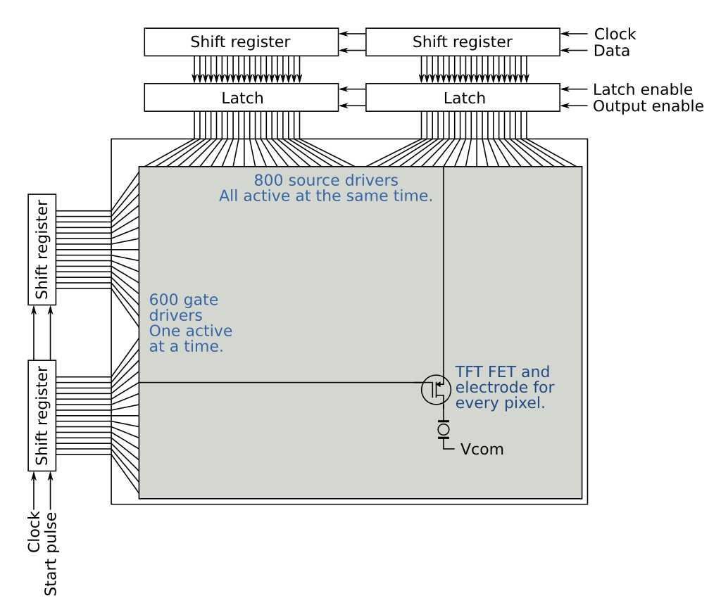 The basic structure of the digital logic on the panel.
The digital signals consist of two sets:
- Gate driver: U1CE1, U1CE2, U2CE1, U2CE2, U1SPV, U2SPV, U1CKV, U2CKV, GMODE1, GMODE2 and RL.
- Source driver: CL, LE, OE, SPH, SHR, D0-D7.
The gate driver is a bit of a mystery: the multitude of signals apparently allows you to chain the two halfs of the display in different ways. However, it is not really described in any public materials, so I just went and copied the arrangement from the available schematic. Connecting U1SPV & U2SPV, U1CKV & U2CKV and GMODE1 & GMODE2 pairwise together causes the gate driver to neatly advance row-by-row from first half of the display to the second half. For some reason, the chip-enables are connected so that U1CE1 is low and all the others are high.
The source driver is somewhat simpler: the few individual signals are the clock, latch enable, output enable and start pulse for the logic. Basically it is a 2-bit 800-deep shift register followed by a latch. One display row is shifted into the register, loaded onto the latch and then strobed to display using the output enable.
There is nothing special about driving these signals. You can just connect them to whatever IO-pins you have free. Only point of note is that they are all 3.3 V logic level.
Odds and ends
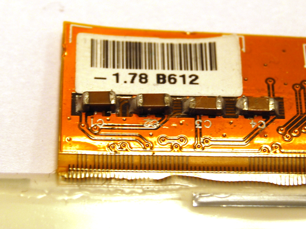 The Vcom label on the display, specifying voltage of -1.78 V.
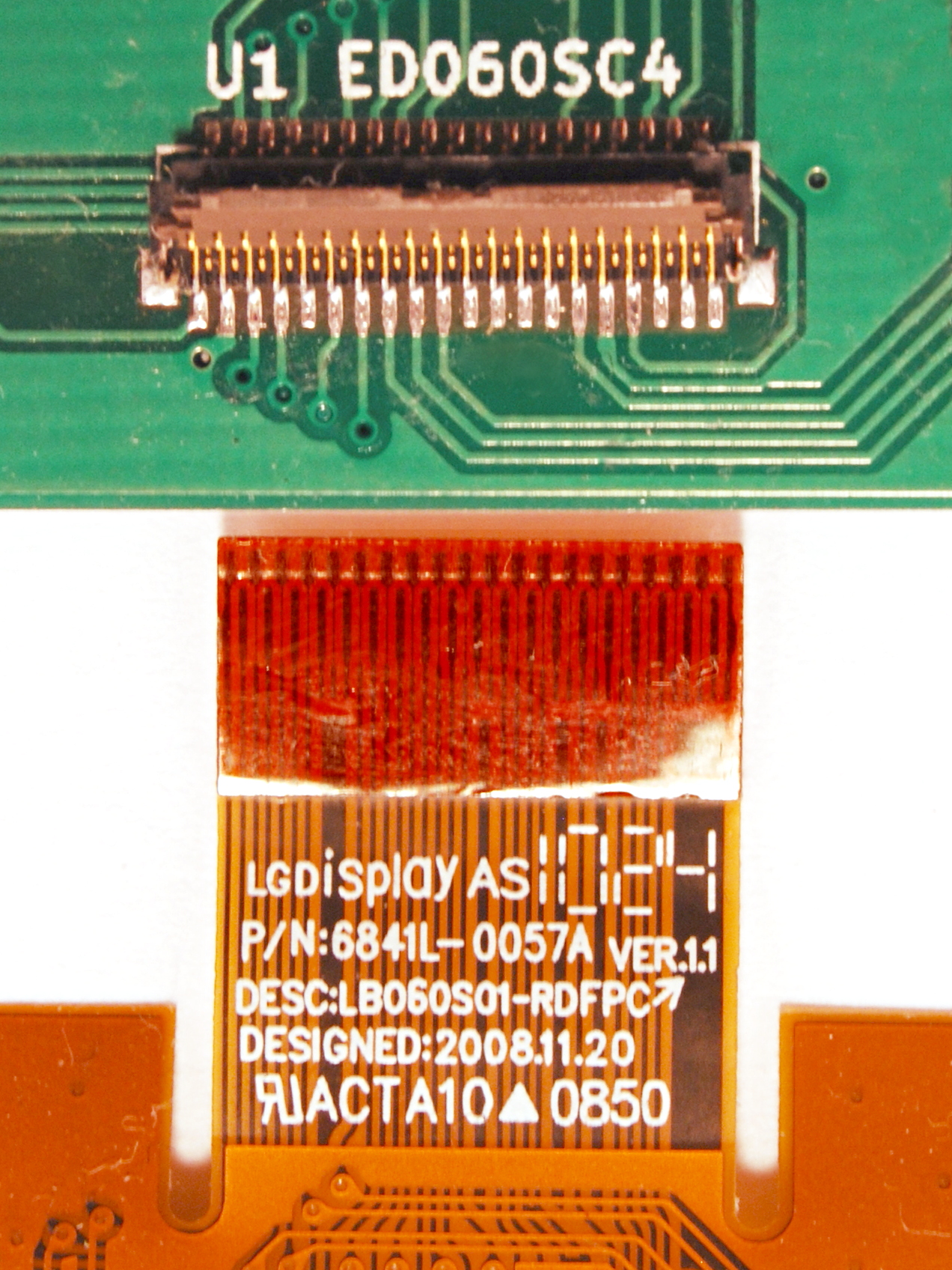 FPC connector for the panel.
There are still a few signals I haven't covered yet. The SHR and RL digital signals are supposed to switch the direction of the source and gate shift registers. However, atleast on my panel they seem to do absolutely nothing. Even if they did something, mirroring the image is easily done in software also, so you can safely connect them to ground to save IO pins.
Vcom is an important voltage input. It is the common electrode on the front side of the display, and it provides the reference voltage against which the driving voltages act. There is a display-specific optimal voltage that gives the best display, and it varies between 0 V and -2 V. The correct value is usually written on a sticker in the panel, but if it isn't, -1.5 V is probably a good guess.
Vborder, on the other hand, is a useless voltage input. All it does is shift the color of the screen border. I guess it's purpose is to make the border color match the content on the screen, but frankly I do not find that important enough to waste a pin. You can just connect it to ground if you are happy with gray border color. For the more adventurous people, +15 V or -15 V may be interesting choices also.
Vdd and Vss are just plain old +3.3 V digital supply voltage. I have connected this directly to a IO pin, so that I can easily switch it off when the display is not in use. If you don't mind the 1 mA power draw, you can probably just connect it directly to supply voltage.
The connector on the display itself is also a bit interesting. The datasheet specifies it as 39FXL-RSM1-S-H-TB from JST, but this turns out to be a very difficult to source. Fortunately FH26-39S-0.3SHW from Hirose is compatible and available on e.g. Farnell.
Pulling it all together
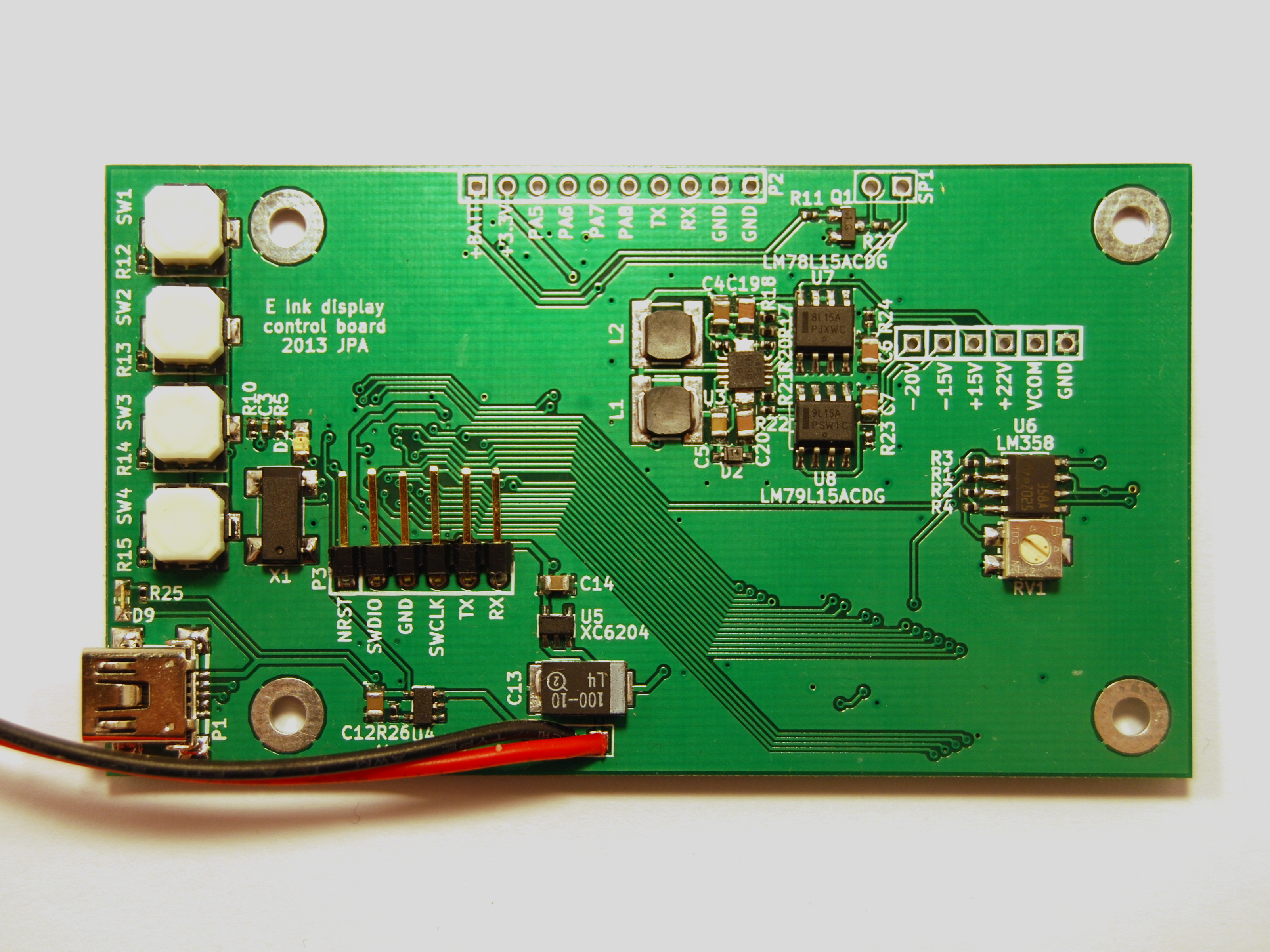 My controller PCB.
Here is an example schematic on how to connect the ED060SC4V2 E-ink panel to a STM32L151 microcontroller. With small changes, it should work just as well for most other E-ink panel types.
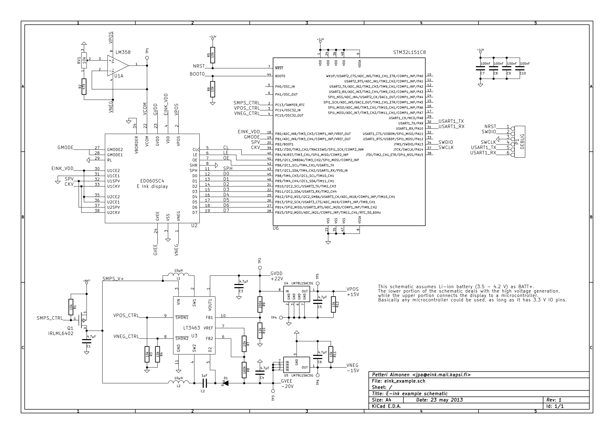
The PCB's I'm using have a bit more stuff on them as it is going to be a part of a functional device eventually. But more on that later, this series focuses on the E-ink driving itself.
You can download the Kicad schematics here. I don't have a PCB layout that matches the example currently, because my first proto had a bunch of errata.
– Petteri Aimonen on 24.5.2013