
Spin plate for taking 360° photos
This idea came from a three-phase brushless DC motor that I had disassembled from a broken hard drive. Having made enough persistence-of-vision displays for a lifetime, I needed some other use for the motor. Ergo, a spinning platform for taking 360° photos of things.
The goal was to have a plate that would spin a set amount (say, 30 degrees), stop, be still for a few seconds while a picture is taken, and repeat. The images could then be combined to a draggable 360° view like this:
Design
 Holes carved in the bottom plate.
 Everything sits snugly in its own compartment.
The basic design is trivial: two round pieces of plywood, with the motor mounted in between. Because the motor has plentiful screw holes, it is easy enough to have it bolted rigidly in place. Then all that is needed is a microcontroller to drive the motor, a battery for power source and a potentiometer to control the speed of spinning.
Having cut the discs using a scroll saw, I used Dremel to carve recesses for the electronics and the motor. Getting the height right for the motor (to leave a suitable gap between the discs) turned out to require some trial and error, and finally I had to add a piece of rubber under the motor so that the tilt can be adjusted.
The electronics are very simple and are based around the STM32L151 microcontroller and BSH105 MOSFETs. I first intended to do some microstepping, which is why I chose the STM32 with its flexible PWM features. However, things did not go quite as planned..
The problems
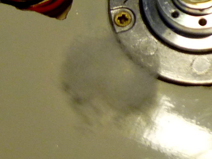 Critical damping, a.k.a. cotton wad superglued to the disc.
First off, the mass of the disc combined with the very smooth running bearings of the motor turned out to produce a very good harmonic oscillator. What that means is that the plate wouldn't stop at the target position, but would instead go past it, slow down, return, overshoot again and just keep oscillating back and forth. In practice, the oscillations would continue for more than 10 seconds. In principle, this was a simple problem to fix. Adding some friction between the discs provides for damping, which speeds up the decay of the oscillations. With enough friction, the plate would stop at exactly the target position (called a "critically damped" system).
Second problem was the PWM, interacting with the motor coils. I had forgotten to include flyback diodes in the design, but they were simple enough to add on the PCB. What wasn't as obvious was that the coils wouldn't pass much current when you pulse it at 20 kHz, and anything less would result in an acoustic annoyance. Fortunately, adding some 10µF capacitors in parallel with the coils was enough to make the response more linear. I guess with the capacitors in place, the flyback diodes aren't strictly necessary either.
Now that I supposedly had the motor going where I wanted, and it also staying there, the rest should have been a piece of cake. But of course it wasn't so.
The battery I was using was an old 500 mAh Li-ion cell I had pulled from a broken MP3 player. The motor was from a old 3.5 inch harddrive, and didn't have any qualms about using as much power as it wants, especially at these very low RPMs that it was never designed for. Consequently, as soon as I had the motor running for more than a minute, the battery protection circuit would decide that the average current was too high and cut off the power. I did have a bunch of 18650 cells, but they were too high to fit in the available space. I could have bought a cheap cellphone battery, but most of them aren't designed for continuous > 1 ampere operation either. So choosing the laziest option, I decided to turn the motor off every now and then, and run it at reduced current. However, this meant goodbye to the microstepping ideas, because there was no chance of having enough current to power two coils simultaneously.
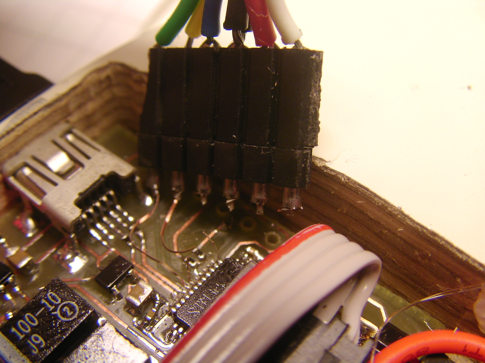 The traces lifted off very beautifully!
The final straw was when the programming connector on the PCB broke apart and took the traces with it. No more debug UART, no more reset button. The connector was so weak because of height limits: I had to mount it on the copper side of the PCB. Without the added support from the holes, a very slight force on the connector was enough to tear up the pads from the PCB. Fortunately I was able to solder wires for the SWDIO, SWCLK and GND pins, which are all that one really needs for programming an STM32.
At this point I was getting quite fed up with what was supposed to be a quick weekend project. I decided to just implement very basic "step forward every N seconds" program, screw the thing together, paint it and call it done.
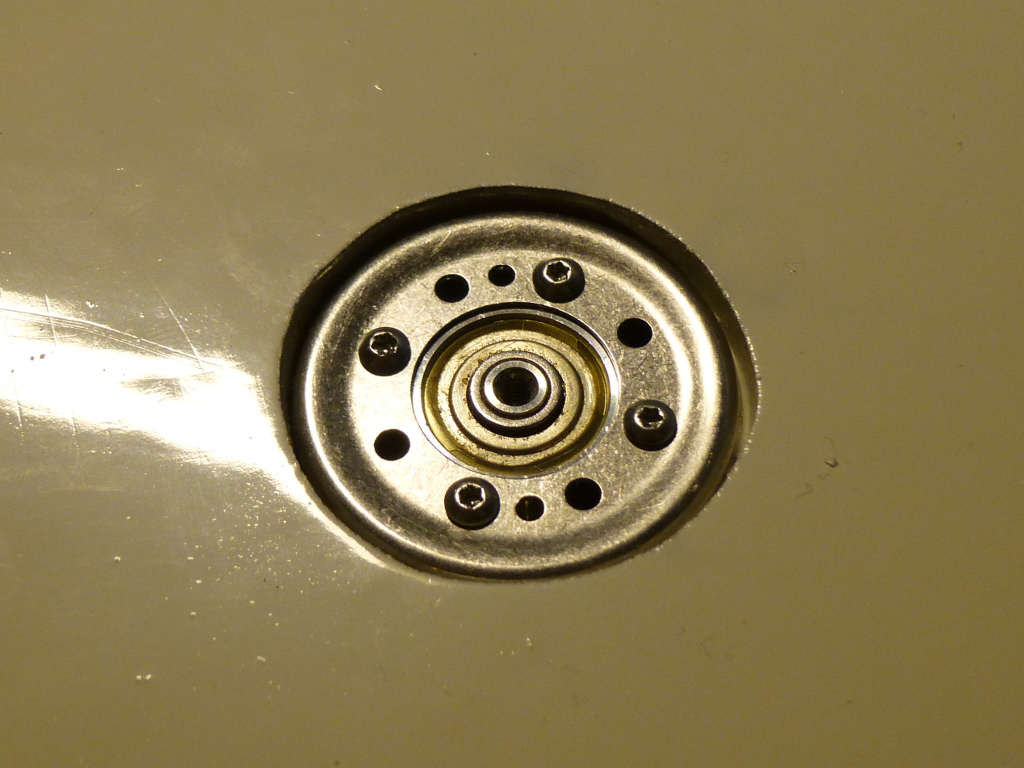 I had to cover up the motor mount somehow.
I hadn't really considered how I was going to cover up the top part of the motor mounting. Again going the lazy way, I just decided to apply some filler and paint over it. Naturally this meant that I wouldn't be able to easily disassemble it later, but why would I even have to..
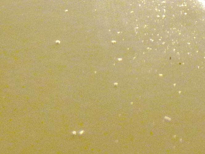 These dust particles just kept coming back!
I opted for a glossy paint, to get that nice Apple-style reflection that fades to white. The first coating had terrible amount of dust all over it. No problem: sand it down, apply some shower magic, repaint, do everything to reduce the amount of dust landing on it. Observe the exact same results. Along the road, I also managed to ruin a few coatings by turning it over, to paint the other side, too soon. After several tries and a lot of sand paper later, it became obvious that the paint can I was using had collected some dust itself along the years. There was no way I was going to get a smooth finish with that paint, and I didn't really feel like doing the paintjob again anyhow. So I just sanded it down to a matt finish, where the dust is not so easily visible.
Now that it was painted and charged up, I was all set to trying it out with a camera. I had of course tested it well before applying the filler, because I knew any adjustments would be impossible. So imagine my surprise when I see it skipping steps..
Looking carefully at the motion, it would clearly oscillate much more on one side than the other. Sometimes the oscillations would continue longer than the motor is on, and the plate would spin uncontrolled to the next or previous position when the microcontroller turns the motor off. Apparently my critical damping wasn't so critical anymore.
So what went wrong? My best guess is that the sanding I had to do had somehow misaligned the motor. The upper disc visibly wobbles as it turns, and the friction varies. I doubt that trying to bend the plate in order to right it would do any good, more likely it would dislodge whatever screws are still holding it together.
 Not quite a perfect match with the background.
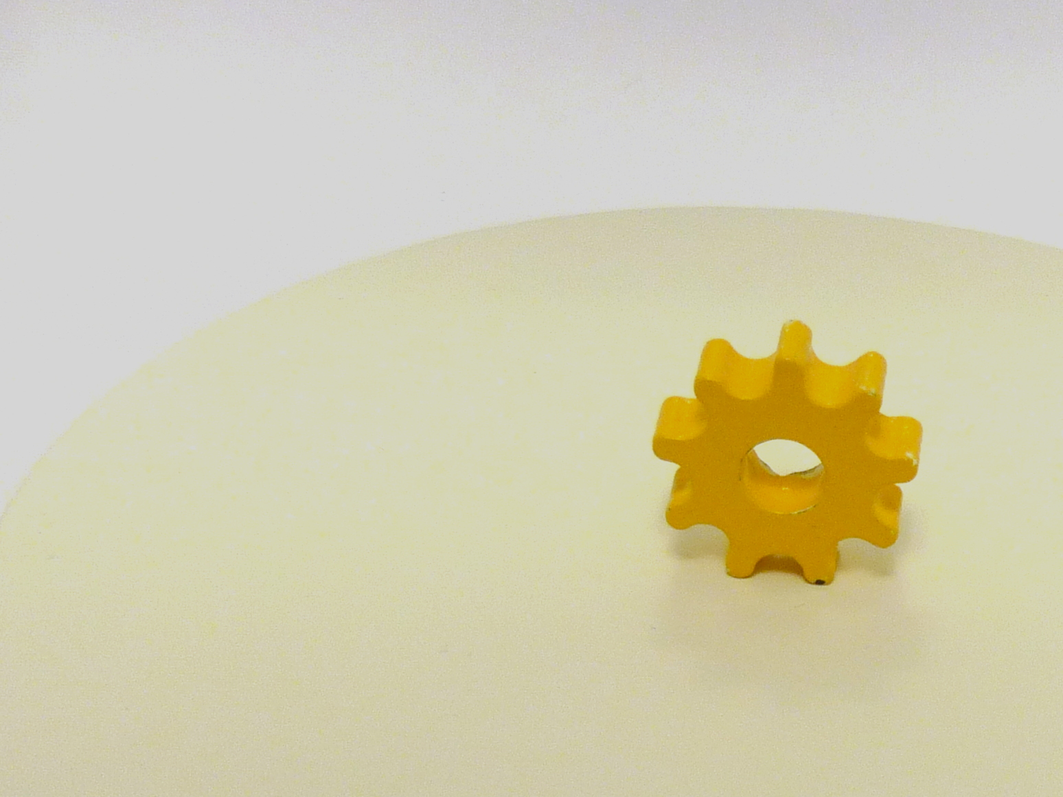
From the photos, one final problem became apparent. Turns out that "natural white" doesn't really fit together with a light box that is covered by white paper. Now every photo requires editing to get rid of the yellow haze.
End result
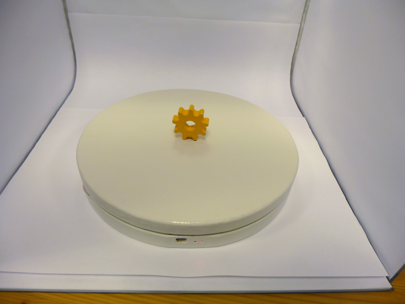 It does look quite neat superficially, though.
This definitely didn't go as planned. But the end result is still borderline useful. After all, the example image at the top of this page was taken with the setup shown to the left. I just need to keep a careful eye on it to notice any missed steps if I want to capture the complete sequence.
If your browser does not support WebM for video, you can either watch on YouTube or download the video.
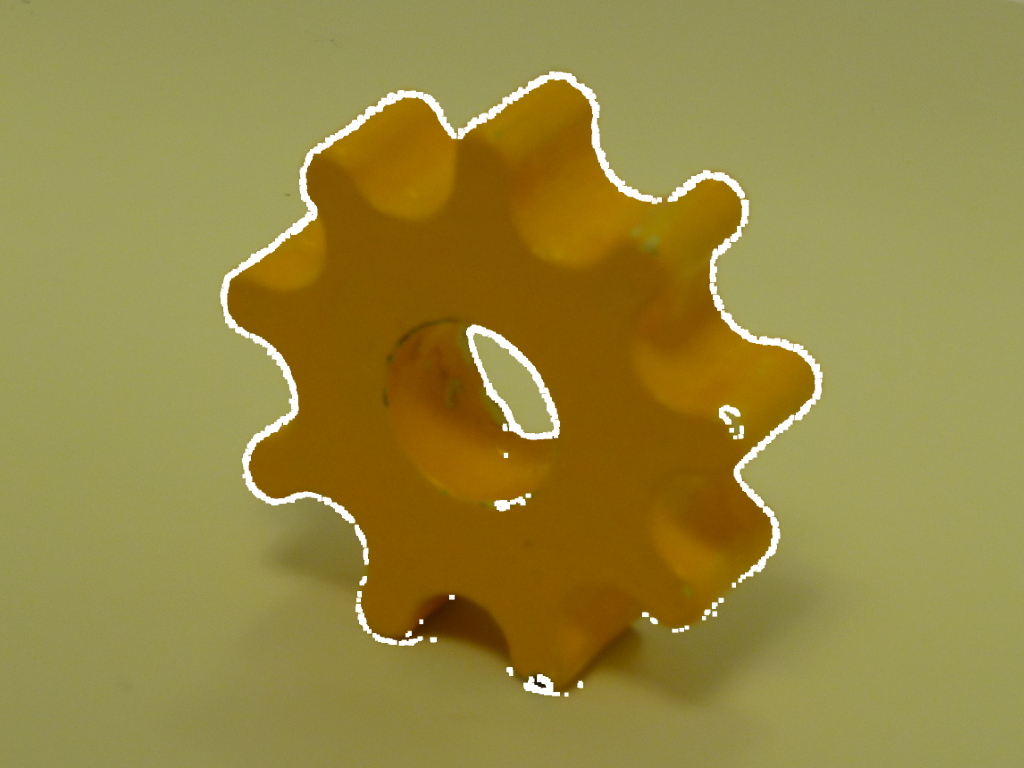 Repeatability test: the overlaid edges are from another photo of the same position.
If there is one thing I'm satisfied about, it is the repeatability of the positions. Despite the heavy oscillations, when I took a photo of the same position in two different rotations, the photos overlay almost perfectly.
In case you have a use for the source code or schematics, they're all here: https://svn.kapsi.fi/jpa/spinplate/.
– Petteri Aimonen on 17.9.2013