Fixing noisy measurements on Owon XDM2041
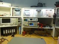
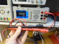
Needing some equipment for automatic testing, I ended up buying a Owon P4603 programmable power supply and Owon XDM2041 bench multimeter. The power supply has been mostly ok, but the multimeter always felt a bit noisy - especially in the 50 MΩ resistance range.
I've never been very fond of sending things back for warranty repair. The waiting is just annoying, and at that point I usually have a lack of trust for the manufacturer. So when Owon support stopped replying after asking a few basic questions about model and serial number, I decided to just open it up.
Power line noise and multimeters
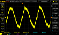
Connecting the leads to a 9.53 MΩ (nominal) resistor gave results that jumped wildly from 9 to 10 MΩ. Touching the cable insulation made the noise worse, so it was quite clear that it was power line noise that was being coupled to the probe cables. It also often showed resistance values even when probes were not connected to anywhere.
Mains frequency noise, at either 50 Hz or 60 Hz depending on region, is everywhere. It will be clearly visible on oscilloscopes if probes are not connected, but the shielded coaxial cables reduce it a lot. For the unshielded multimeter cables, it must be filtered out before showing the measurement to user.
Most low-end multimeters choose to just average measurements over 100 milliseconds. This is nicely divisible by both 50 Hz and 60 Hz, and averaging over the whole cycle eliminates most of the noise. Higher end multimeters often have selectable averaging time, can sync up to the actual mains frequency and may even have software-based notch filters.
What is inside XDM2041?
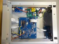
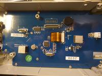
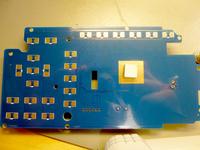
Mostly air. The enclosure is huge compared to what is inside: a small +5 V power supply, an isolated analog measurement board, and a CPU board that doubles as the membrane keyboard.
The CPU board uses GD32F103CBT6 microcontroller, SP2032 RS232 level shifter and YYS37HV-133-A7 display module. In addition to RS232, the connector PCB has holes for a USB connector. Trying to connect to it however shows that while there is a D+ pull-up, the XDM2041 firmware does not implement USB. Curiously, despite all the apparent cost reduction, they've included RTC crystal and backup battery.
The analog board has isolated DC-DC converter for power supply and opto-isolators for SPI bus to the microcontroller. The measurement chip running the show is HY3131, an integrated multimeter chip with 24 bit ADC. The passive components seem to closely follow the HY3131 reference schematic but some pin assignments are different. There is a 4.0 MHz crystal next to HY3131.
What is the XDM2041 averaging time?
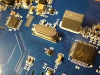
The HY3131 reference schematic has a 4.9152 MHz crystal. The ADC samplerate is determined by a constant 30x divider, and a configurable oversampler with ratio of 256, 512, ..., 32768. With the default crystal, dividers of 16384 and 32768 provide averaging times of 100 ms and 200 ms, which would eliminate mains noise.
The XDM2041 however has a 4 MHz crystal. Probing the SPI bus indicates that the slow speed has 4096x OSR, and the mid and high speeds have 2048x OSR. These give 30.72 ms and 15.36 ms averaging times. No wonder it is so noisy in a 50 Hz country. I guess these settings work a bit better with 60 Hz noise.
Changing the crystal
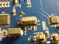
I decided to change the crystal. The closest crystal frequency that gave rates divisible by 50 Hz was 3.072 MHz. This should give averaging times of 20 ms and 40 ms.
I managed to break one of the PCB pads when desoldering the old crystal, but fortunately it was fixable with a piece of wire. At least I don't have to worry about warranty anymore :)
Results
After the fix, the 50MΩ resistance range is much more stable. Using measurement hooks, only the lowest digit of measurements varies by +- 1. Touching the cables still causes a +- 0.2 % noise, but that is still a massive improvement compared to the +- 5% noise.
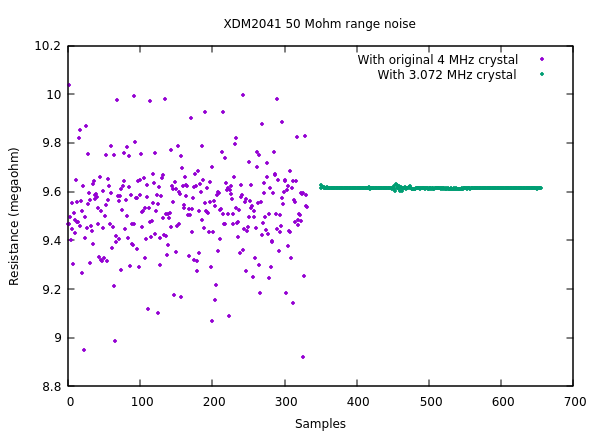
Curiously the false readings with unconnected cables remain, but they are now more stable and disappear after a few seconds. Based on some Youtube videos, it appears some XDM3041 users have similar problems.
As expected, the frequency measurement now shows incorrect results - frequency readings show values that are 30% too high. But I don't use the frequency range much, so it is not much of a loss for me.
I expected that it would also affect the capacitance measurements. But surprisingly the measured capacitances are exactly the same as before.
The voltage and current measurements are also still spot-on when compared against my DIY current/voltage reference.
The timestamps of the record function are based on CPU time, so they are unaffected.
Alternative fixes
An alternative fix could be to add a series inductor and capacitor across the ADC pins, tuned to suppress the 50 Hz frequency. I'm not sure how this might affect measurement accuracy, and I didn't try it.
Owon could also fix this issue with a pure software fix. Setting the ADC to 256x oversampling would give data at 520.8 sps. This could then be downsampled in software to get 10 sps.
Open source firmware?
With all its failures, XDM2041 is a surprisingly accurate meter for its price. Some parts of the hardware are also well-built: buttons work well, the display looks good and the connectors seem decent. The lack of features in the firmware is clearly a market segmentation technique: the XDM3041 looks very similar but has a lot more features and three times the price.
The hardware is simple and easy to follow. Development tools and documentation for GD32F103 are available. The datasheet and application note for HY3131 are available also. I haven't found the documentation for the display, but it appears to use a 8-bit parallel bus that could be probed to find out the register settings.
The debugger pins are not brought out, but the BOOT0 pin and serial port are available on a pin header connector. The debugger pins go to buttons, so they can reasonably be double-used when needed.
The original firmware is of course read protected, but thanks to the work of Johannes Obermaier & co, it is quite easy to circumvent. It appears to have a 8 kB bootloader at the beginning of the flash. The main firmware takes 111 kB, a large part of it fonts. In the last 2 kB of the flash there appears to be some configuration information, perhaps the calibration or just the user interface settings.
It should be possible to make a custom firmware for this, enabling a lot of features like graphing and math functions. It seems that hardware-wise it should be possible to have up to three simultaneous measurements: two voltages and one current measurement.
But I have too many projects already, so I think I'll try to pass up on this..
– Petteri Aimonen on 27.6.2021
