Big wheels
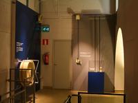
I did my civil service at a local museum. As a side project, I was assigned to "create something that demonstrates how mechanical power transfer works" for the steam engine room. This is what I came up with.
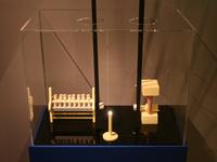
It has a crank for spinning up a flywheel (1:10 replica of the real 8 meter diameter flywheel). Ropes transfer the power to a second pulley, from where it goes through a clutch to a belt cylinder. Finally, it drives a small dynamo and a spinning machine.
Some of this stuff is heavily inspired by the plans the museum had previously had with the Department of Mechanics and Design of the university. However, those plans had got stuck when the mechanical engineers were more interested in building a miniature version of the steam engine – despite the fact that the real-size 1200 kW beast is right there in the museum.
First of my designs were also quite small. After some feedback the device ended up filling the whole corner. We were a bit worried about getting the 1300 EUR expense approved by the administration, but there was no opposition whatsoever. I particularly like the transcript note "It has been the intent that a demonstration shall be built. Therefore it was decided that it will be built according to the plan." for its vagueness :)
Wheels
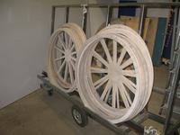
The wheels are made of watercut plywood planes, glued to eachother and secured with bolts all the way through. There are a total of 40 sheets in the large wheel.
I might have been able to make the wheels manually, with a technique something like these bandsaw wheels, but going with the watercut parts was a lot easier. It cost 700 EUR, though.
Mechanics
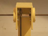
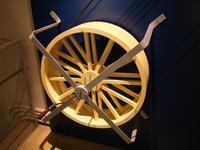
All other parts were off-the-shelf parts or handmade from common materials, such as plywood, flat and round iron bar and 30 mm aluminum rod. The axles are 10 mm and rotate on ball bearings, which were fit into a suitable hole cut into the plywood.
A bit more intriguing part is the clutch. I decided to add one, as there had to be some means to disconnect individual factory rooms from the power. It is mostly fiction, though, because I haven't seen what kind of clutches they really used. The clutch I made is operated by a lever, with is connected to a cam. The cam in turn pushes a rod upwards, which turns another rod, which finally pushes a connecting cylinder off the axle end. The cylinder has a square hole to transmit torque between the two axles.
Display
The demonstration is currently (and I assume until it gets broken) on display at Työväenmuseo Werstas, Tampere, Finland. I must thank all the wonderful people working there for the excellent texts and visual looks of the completed system.
Here is a short video of it in action:
If your browser does not support Ogg Theora for video, you can either watch on YouTube or download the video.
– Petteri Aimonen on 19.5.2011
