
Automatic dog collar light
My parents live in the countryside, so they often let their dogs run free in the yard. The dark winter evenings tend to make the dogs quite invisible, which is both annoying when trying to call them back inside, and dangerous if they should roam towards the road. This is a light that can remain attached to the collar and turns on automatically when needed.
Idea

Having a light attached to the dog's collar is a simple solution to the visibility problem. However, turning it on and off and changing batteries would be quite a hassle, and many lights wouldn't even survive the rough ride.
The light is needed when: 1) it is dark, 2) the dog is outside and 3) the dog is on the move. A clock can tell when the sun is up. Being outside can be detected from temperature. And an accelerometer will tell whether the dog is moving or just sleeping in the pen.
I estimate that the light will be needed for about 1 hour daily. To give some margin for false positives, let's say it is on for 4 hours. The best battery capacity available at this size is probably a non-rechargeable lithium battery like the 900 mAh 3 V CR14250. The darkness in Finland lasts about 6 months or 180 days, so the light can use about 900 / 180 / 4 = 1 mA when active if I want the battery to last whole winter.
This is quite achievable by making the led blink when on, which decreases the current draw while keeping it noticeable. Naturally it is also important to minimize any standby power draw and to make the detection as accurate as possible.
Electronics and enclosure
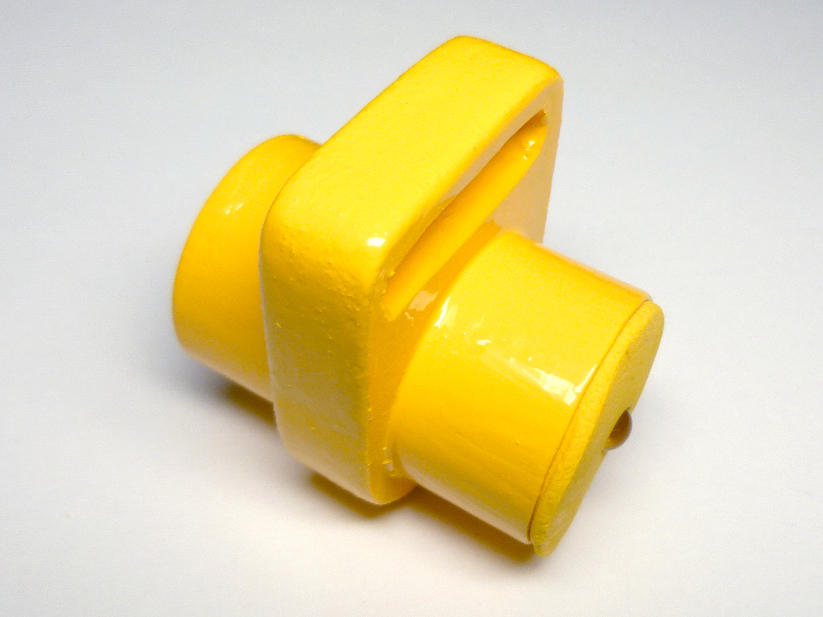
 Evolution of the rubber plug.
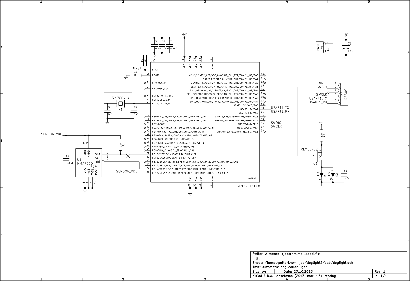
The circuit is based on the STM32L151C6 microcontroller and MMA7660 accelerometer. While they are both quite low-powered devices, there are probably even lower power alternatives on the market. These were just what I happened to have in my box.
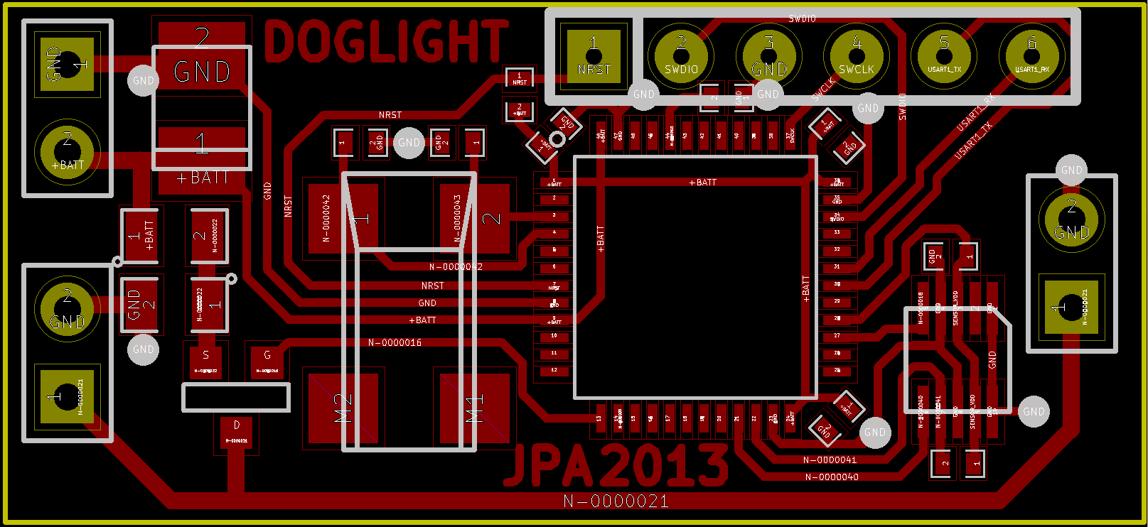
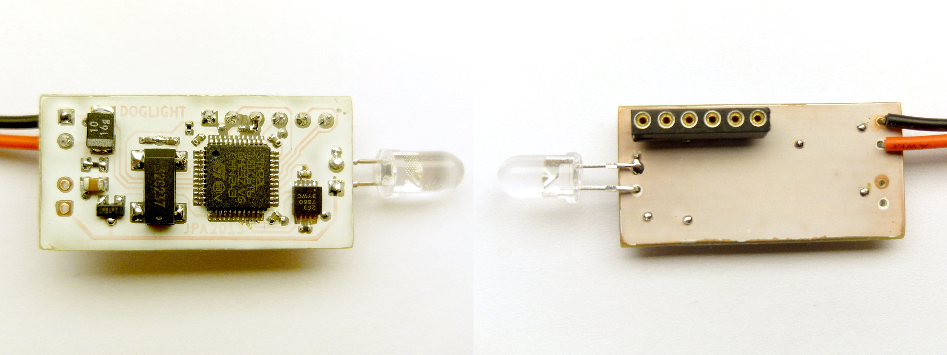
The PCB is designed to fit inside a 25 mm PVC pipe, with a led poking out at each end. Because I'm using the STM32L151's internal temperature sensor for detecting the outside temperature, it is important that heat conducts well from it to the pipe. For this purpose I use a silicone thermal transfer pad between the chip and the pipe.
I cut out a piece of 1 cm polycarbonate for attaching the pipe to the dog's collar. One end of the pipe was sealed with thinner polycarbonate, superglued into place. The open end was sealed with a rubber plug that I made out of Oogoo.
Software
The software is based around a simple state machine:
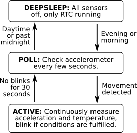
In the ACTIVE state, the sensors are read continuously. The accelerometer readings are passed through a band-pass filter, which aims to detect oscillations with a period of 0.2 to 2.0 seconds, i.e. a running or a walking dog.
The temperature readings are processed using a sliding derivative and average filter. By noting the rate of change and knowing the thermal conductance, the outside temperature can be estimated even before the chip itself has reached equilibrium. This speeds up the response when moving between indoors and outdoors.
Each of the sensor results is rated on a scale of 0 to 100 %, where 100 % means the highest probability of "should blink". The ratings are multiplied, and the result is used to decide the blink frequency. At low probabilities, the device conserves power by increasing the interval between blinks. This also means that the light won't just suddenly turn off and on as conditions change, but will fade between the states more smoothly.
Furthermore, the device also has built-in schedule for when the sun rises and sets, and also the likely times of when the dogs will be let out. I.e. it will not waste power at the middle of the night or during daytime, and it should also adapt to lengthening day in spring. The schedule is also expressed as a probability, and it is used to modify the poll interval for further power savings.
Power measurements
I measured the power consumption in the various states:
| State | Supply current | Estimated time daily | Estimated energy daily |
|---|---|---|---|
| DEEPSLEEP | 2 µA | 14 h | 28 µAh |
| POLL | 6—22 µA | 8 h | 120 µAh |
| ACTIVE | 0.5—2 mA | 2 h | 2000 µAh |
The supply current in POLL and ACTIVE states varies based on the schedule and sensor values (i.e. less power used when movement is less likely). A rough total of these gives an average consumption of 100 µA, which should give a battery life of over 9000 hours or about 1 year.
However, cold temperature will definitely reduce the battery capacity, so it remains to be seen whether the target of 180 days will be met.
Results
Having an accelerometer hanging on a dog's collar can give some interesting data. I set up the software to record various information, including the movement and temperature values as histograms, along with trivia such as "time spent in freefall". These are all stored in the 4 kB EEPROM of the microcontroller.
Cugu, winter 2013-2014


Cugu's light stopped working after about a month of use. The reason was excessive structural damage from canine teeth, i.e. Skeanka found it very fun to grab and bite the light. None of the other dogs are as fond of biting things, consequently Skeanka's own light is still working well.
After another month laying around somewhere in snow, I found the electronics. Surprisingly enough, it was relatively undamaged, and I was able to read out the statistics: stats-cugu-201402.txt.
Some observations:
- Total working time was 1951379 seconds, i.e. 23 days.
- Energy used was 103 mAh, i.e. 11 % of battery capacity. This gives a total battery life of about 200 days, which is in line with the estimates.
- Freefall time was 15 seconds, i.e. 0.003 % of recorded active time.
- Active time was 5 hours per day, which is somewhat more than expected.
- The movement estimate is 0 % at 40 mg and 100 % at 140 mg. There is not a good distinction of values in the raw movement histogram, but it appears that a second peak is at 130 mg.
- The temperature histogram is divided well between the outside temperatures around 0°C, and the inside temperatures around 23°C. Apparently being close to the dog rises the temperature about 5°C.
Skeanka, winter 2013-2014
Skeankas light worked fine from December up to April, at which point days were light enough that it was not needed anymore. Approximately 40% of battery capacity used.
Statistics: stats-skeanka-201404.txt.
Some observations:
- Total working time was 14043413 seconds, i.e. 162 days.
- Energy used 368 mAh. Unsurprisingly, the power usage is smaller in spring as the sun rises earlier.
- Freefall time 70 seconds, i.e. 0.0003 % of recorded time, or about 1/10 of the same for Cugu.
- Active time 4 hours per day.
Conclusion

The light has been in use for a few weeks now and seems to be working. In fact, it is working well enough that I decided to make another unit for the other dog.
In retrospect the placement of the LEDs could have been more symmetric, as now one end sticks out much more than the other. Also the thermal conduction could be improved, now it takes almost a minute for it to detect the temperature drop.
The visibility is satisfactory, but could be better. If the battery statistics are over the first winter look promising, I may increase the blink frequency to make it more visible.
KiCad schematics and firmware source code are available here.
– Petteri Aimonen on 9.1.2014