
Voltage and current reference

When developing a data acquisition system, I ran into a need of having fairly accurate current reference to compare against, 0.1% accuracy or better. This is not a particularly high standard, but unable to find a suitable device in my price range, I chose to design my own.
EBay has plenty of high-accuracy voltage references available, but not many current references. There is also DMMCheck, but it is a bit too expensive for me.
Three approaches to high-accuracy references
The gold standard when it comes to calibration references is tying them to some reproducible physical behavior. For current references, that would be a Kibble balance and could achieve accuracy on the level of 0.1 ppm (i.e. 0.00001%). Obviously that is not cheap or easy to build.
The next level down is building a very stable reference, and then measuring that against such a gold standard. This is the approach usually used in accredited calibration laboratories, and there are DIY projects for high-stability references also. But typically such references have a fairly poor initial accuracy, so they are of no use if you don't have something to calibrate them against.
And then there is the cheapest way: just buying off-the-shelf parts and relying on their initial accuracy specifications from the manufacturers. Typically the manufacturers will laser trim the parts to be as close to the specification as they can, and then measure a large batch of devices to determine how good accuracy they can guarantee. It is hard to find parts with better than 0.01% accuracy, but that is good enough for me.
Part selection
To start with, I searched Digikey for the most accurate voltage reference that wasn't ridicuously expensive. Currently that is ADR45xxBRZ, with ±0.02% accuracy and selling at 6.70 EUR. There used to be a more accurate part X60008 with ±0.01% accuracy, but that is no longer available.
For my purposes, the 2.048 V model was most suitable, while the series has options up to 5.0 V output voltage available. The B grade has ±0.02% initial accuracy, but on top of that there is up to ±0.02% shift due to soldering heat and further ±0.02% temperature drift over the -10°C to +80°C temperature range. One can try to minimize these by careful soldering technique and by using the device in room temperature.
To make this into a current reference, a precision shunt resistor is also needed. I chose a 100 ohm 0.01% model, which gives 20.48 mA reference current. This is large enough to get suitable accuracy, but low enough to avoid any excess heat that could affect the accuracy.
The current through the resistor is controlled through a transistor, which in turn is controlled by a low-offset operational amplifier. The goal is to make the voltage over the shunt resistor exactly equal to reference voltage, and any input offset would cause inaccuracy. I chose MCP6V51T, which has input offset of just ±2.4 µV, well below the ±410µV inaccuracy in the voltage reference.
The BOM is available below:
| Reference | Part number | Price (EUR) |
|---|---|---|
| U1 | ADR4520BRZ | 6.70 |
| U2 | MCP6V51T | 1.20 |
| D1, D2 | 3 mm LEDs | 0.20 |
| R1, R2, R4, R5 | Basic 0603 resistors | 0.20 |
| R3 | 100 ohm, 2512, 0.01% resistor | 2.30 |
| C1, C2, C3, C4 | Basic 0603 capacitors | 0.20 |
| Q1 | BSH105 or other logic level N-MOSFET | 0.40 |
| Q2 | NJT4031 or other NPN power transistor | 0.30 |
| J1 | 2x6 pin header | 0.50 |
| SW1 | Power switch | 0.50 |
| BT1 | 9V battery connector | 0.40 |
| Enclosure | HH-3431-BCB | 5.70 |
| Total | 18.60 | |
Schematic
The voltage reference is easy to connect, as it only needs input and output capacitors specified in the datasheet. I added a led with a voltage divider to indicate when battery voltage drops below 5 V.
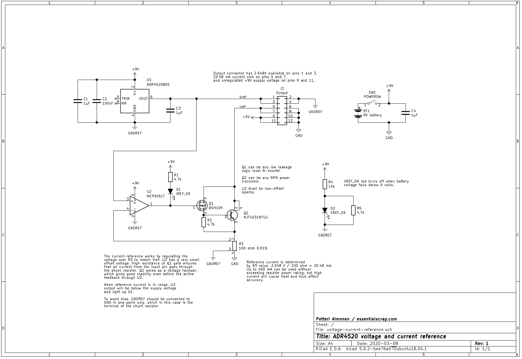
For the current reference, I took a design from TI appnote AN-31. The original design uses a combination of JFET and NPN transistor, where the JFET provides isolation to ensure that all current coming from the input pin goes through the shunt resistor. Nowadays JFETs are somewhat uncommon, but MOSFETs have gotten better and are a good substitute. In fact, one could probably just use a MOSFET and skip the NPN altogether.
For accuracy, the shunt resistor connection is important. Circuit board traces and solder joints can have a few milliohms of resistance. This may sound tiny compared to the 100 ohm shunt, but ±0.01% tolerance means a difference of just ±10 mohm.
To remove any offset, the low current measurement traces are routed to resistor pins separately from the higher current load connections. Because the voltage reference is ground-referenced, I chose to have two separate ground nets (GNDREF and GND in the schematic) and connect them at the shunt resistor. This does cause the operating current of the voltage reference and the opamp to go through that connection, but it is still an order of magnitude less than the load current.
The current reference is configured as a sink. The actual load current can come from either the 9 volt battery or from an external source and the reference will sink it to the ground connection. A led indicates when opamp output is below supply rail, which only happens when the load current matches the reference - this helps catch any connection errors or insufficient supply voltage.
Circuit board
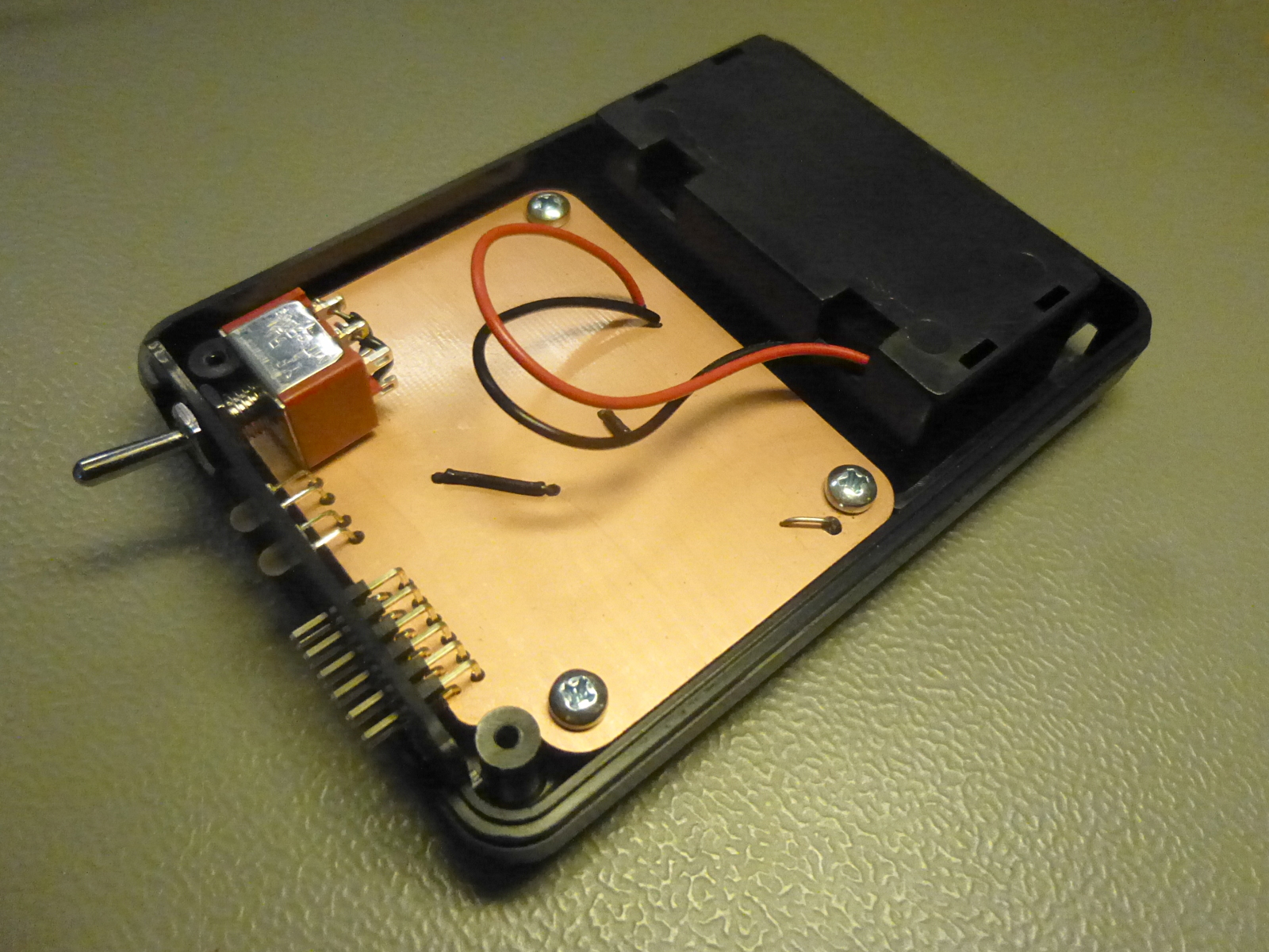

The PCB is a 1.5 layer design that is easy to manufacture at home by milling or etching. It is designed to fit HH-3431-BCB enclosure. The size is larger than would really be required for the circuit, but this leaves sufficient cooling area for the shunt resistor and power transistor. At 20.48 mA current that is not very important, but the same design should be useful for up to 204.8 mA current by just changing the resistor.
Expected accuracy
The voltage reference accuracy can be taken directly from ADR4520 datasheet. Depending on soldering and operating temperature, the accuracy can either be considered as ±0.02% in room temperature and carefully manually soldered, or ±0.06% over full temperature range and high-temperature reflow soldered.
The current reference accuracy is ±0.01% worse due to the shunt resistor tolerance. The opamp offset voltage and any voltage drop in the PCB traces should be insignificant compared to that, giving a ±0.03% total inaccuracy in room temperature.
Testing
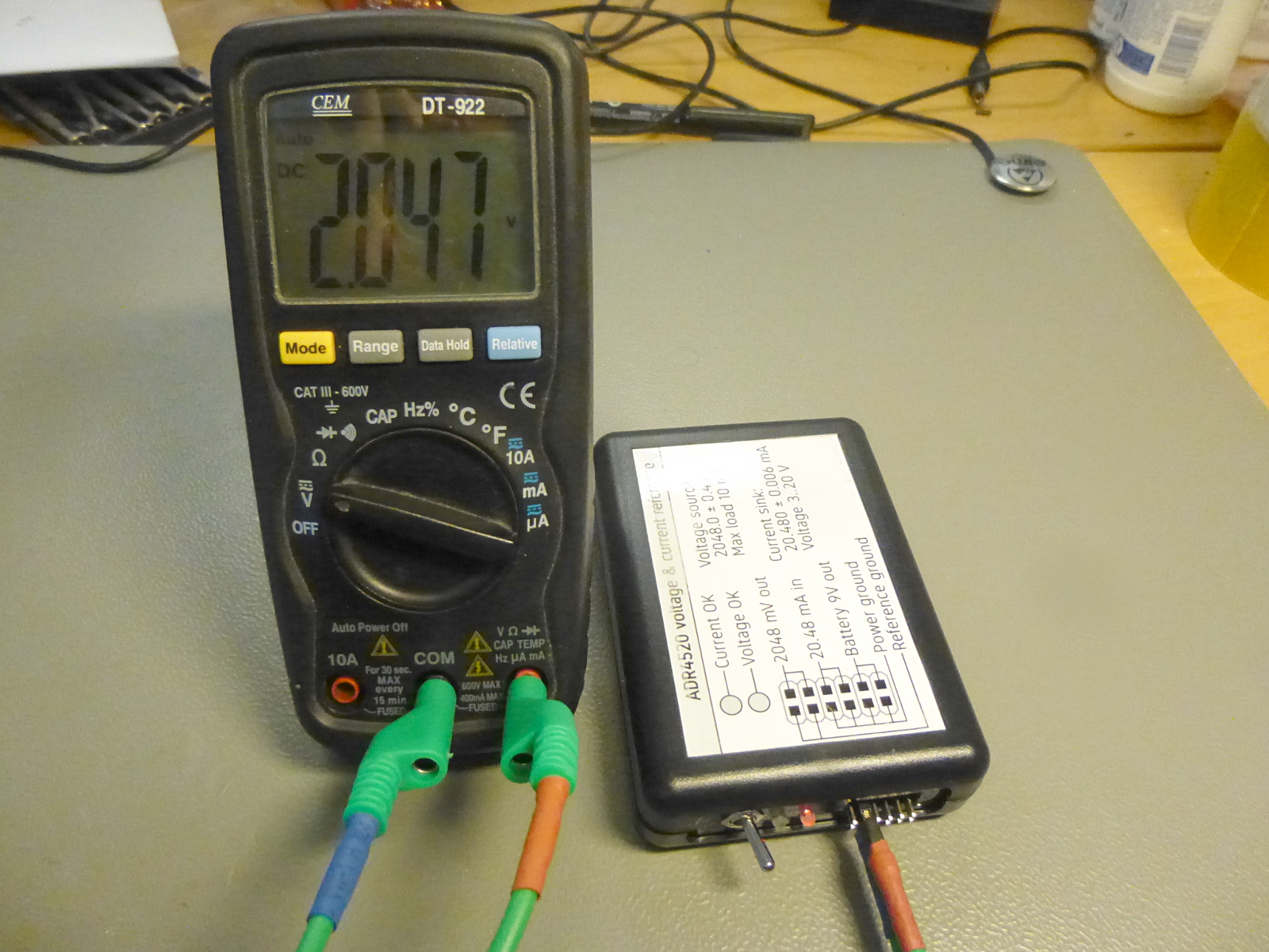
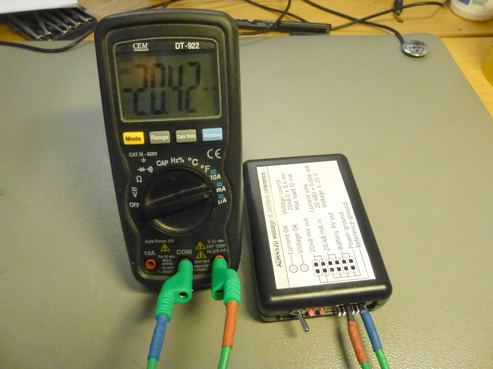

The basic connections for testing a multimeter are voltage measurement between GNDREF and VREF pins, and current measurement between 9V and IREF pins. I guess I could have brought out the 100 ohm resistor pins to make it possible to test resistance measurement accuracy also.
My basic DT-922 multimeter was well within its ±1% accuracy specification.
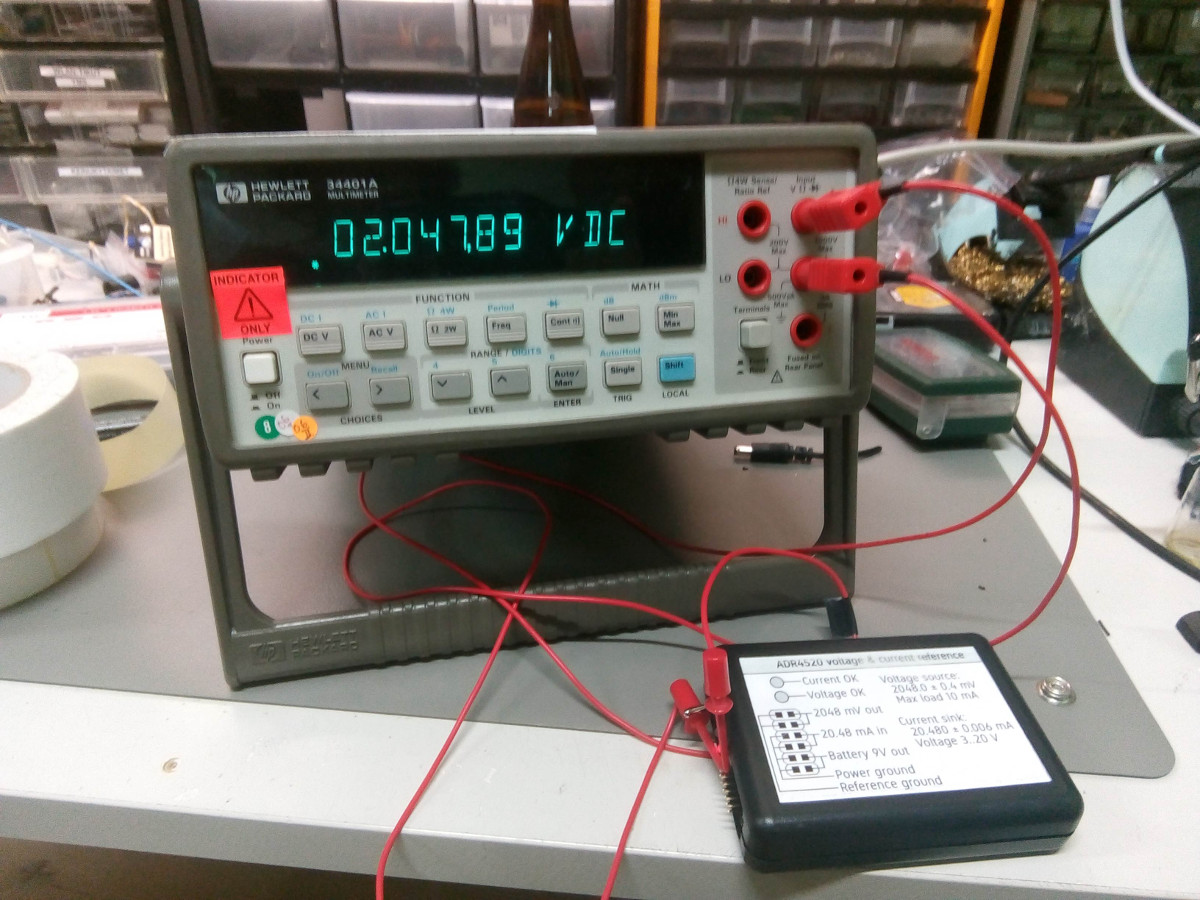
Our hacklab has a HP 34401A which has a specified voltage accuracy of ±0.004% and current accuracy of ±0.05% for 1 year after calibration. However our unit hasn't been calibrated in well over a decade. The voltage reading of 2.04789 V (-0.005% error) is as close as one could expect and the current reading 20.4962 mA (+0.08% error) is not too far from the expected accuracy limits.
Without a reliable reference it's impossible to know whether the 34401A has drifted out of calibration or if my current reference is a bit less accurate than it should be. But in any case, at least it is well within the ±0.1% I was aiming for.
Files
The KiCAD design files, front panel design and ready-to-order gerber files are available in this zip.
– Petteri Aimonen on 8.3.2020