
Sphere mechanism

The sphere mechanism uses a gear motor and a servo. This seems to be the most popular method in DIY implementations. The alternative is the "car in a sphere" arrangement as envisioned by (among many, I'm sure) xkcd, and implemented by Sphero.
I didn't bother doing much background search beforehand. Instead, I dug up an old mouse ball and drew pencil lines over it to figure out how it might turn. I came up with two ways: a motor and a servo, or just two motors. Having two continuously rotating motors should allow free travel in any direction. The servo arrangement only allows direct movement forwards and backwards, and slow turning while moving.
 Two possible mechanisms
In retrospect, I can understand why the Sphero creators have gone with the car-in-a-sphere approach. That very easily brings the center of gravity close to the shell, which gives the strongest driving force. When there is a motor axis going through the center of the sphere, that necessarily keeps a certain portion of the weight there also.
Frame
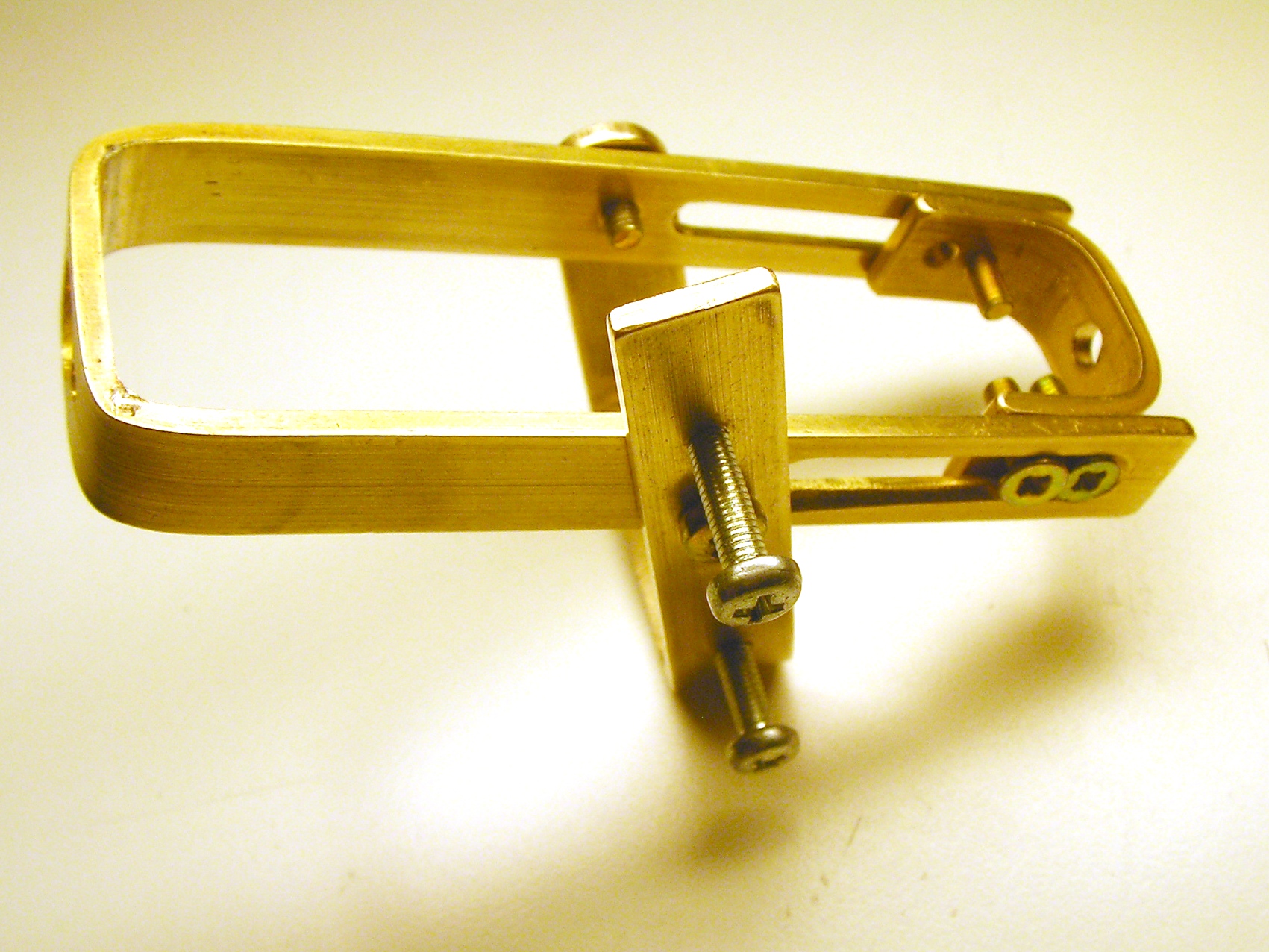 First version of the frame, with bent corners.
 Final version, soldered corners.
Everything is mounted to a spinning frame made of rectangular brass bar. In the final version, the corners of the frame are simply soldered. I spent some time trying to bend the corners, but even after heating and annealing the brass, it was impossible to get sharp and accurate corners using my equipment.
I had to redo the frame twice: first because it was too imprecise, then to change the servo location. The first two versions had the servo mounted on the swinging arm, which really wasn't good for the magnetometer calibration (hint: servos contain motors, motors contain magnets, magnets mess up compasses).
At first, I mounted the battery as weight. Because of the steel casings, also the batteries disturbed the magnetometer. This was a simple fix by just mounting the batteries on the main frame and using some lead fishing weights as the moving weight.
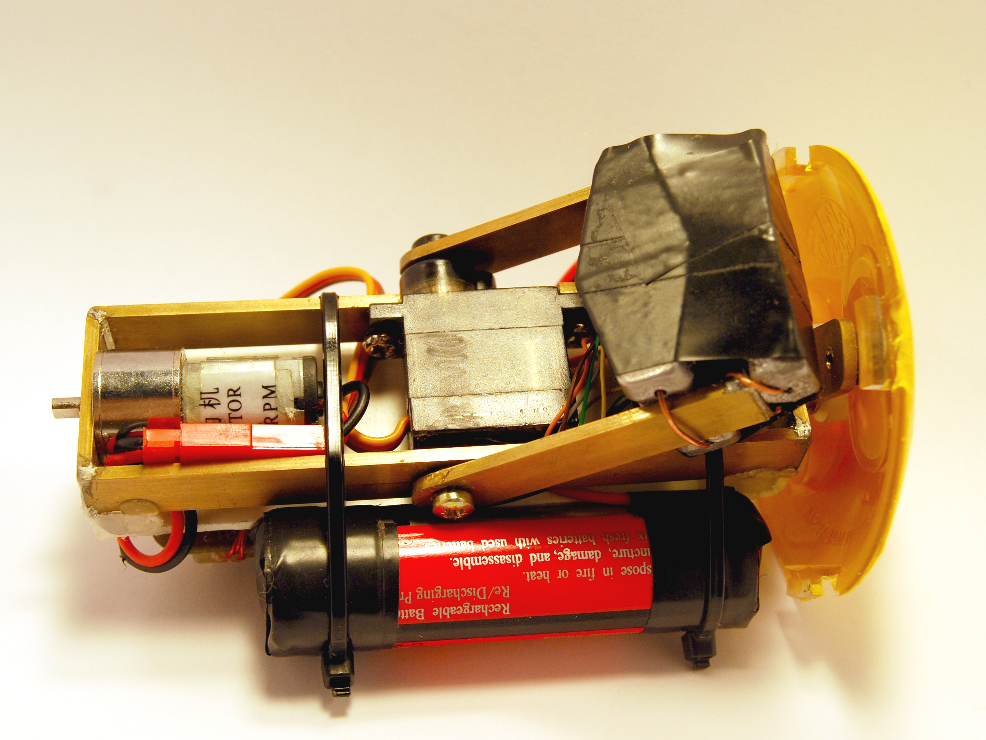
Shell
The shell is a 10.5 cm diameter hamster ball, coated with plastidip. There is not much special about it, almost every DIYer seems to use hamster balls for this purpose. They have a nice opening cover for inserting electronics and are quite strong.
One point to mention is that the battery charge connector is brought out through a hole. It spins with the inner platform, and the axis in this end is a piece of brass pipe.

Performance
The motor is a 1000 RPM 6 V gear motor from eBay. At 4V, it manages some 600 RPM when unloaded, and on hard floor it can spin the sphere at about 200 RPM. This gives a ground speed of 1 m/s. It might have been better to go with a lower RPM motor to get better acceleration.
At the early stages, I had an algorithm monitoring the attitude of the platform to stop the motor from spinning over. This became unnecessary when I increased the moving weight to 130 grams, simplifying the control algorithm a bit. With a more powerful motor such a software limit would still be necessary.
The servo is just a random small metal gear servo. It is definitely fast and strong enough for the purpose, but it sometimes oscillates a bit with the heavy weight.
– Petteri Aimonen on 17.10.2012