Relay multiplexer for lab instruments
I have been adding programmable equipment to my home lab: USB connected power supply, electronic load, multimeter, oscilloscope and function generator. This is great for doing parameter sweeps and long term tests. But often I have more than one thing I want to measure with the multimeter. In this project I build a simple relay multiplexer for selecting signal sources.
Existing alternatives
There are many USB relay cards out there. Cheapest include ICStation ICSE014A and clones of it. Unfortunately it has a very poorly designed protocol which results in accidental changes of relay states when software is restarted. It also tends to draw quite a lot of current when all relays are on, often exceeding USB port 500mA limit.
Better boards like Robot Electronics RLY08C work fine, but are not very convenient for lab usage. I wanted a board that has banana binding posts for cables, and that switches both negative and positive signal as a pair.
Schematic design
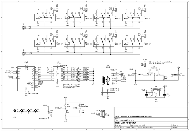
First thing to choose was the relays to be used. I ended up choosing Panasonic TQ2SA-5V for its low coil current and low wetting current requirements. Wetting current in particular can be a problem for lab usage, as the contacts may oxidize on relays designed for high power when the load current is only microamperes. Signal relays have gold coating on the contacts, which does not handle as high current but avoids oxide problems.
The relays are divided into two groups, with 4 relays each. This allows to use the groups in parallel for two separate instruments or for 4-wire measurements. Alternatively the inputs can be joined with pieces of wire to form a single group with 8 relays.
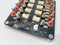
I chose STM32F042 as the microcontroller handling USB connection, because it does not require an external crystal. TBD62783A handles driving the relays. It has integrated flyback diode and input pull-down resistors, making the schematic easy.
I added two push buttons for convenience: first one cycles through each relay in turn, and second one opens all relays. This can be quite useful when you are making connections to test equipment, as you can check that everything works before starting the measurement script on PC.
Even though the relays chosen have relatively low coil current, the total current for 8 relays and the indicator LEDs still climbs to over 250 mA. To avoid voltage spikes when all relays get switched simultaneously, a large enough capacitor is needed. The 470 µF I chose is probably larger than needed, but better play it safe. Having more than 10 µF capacitance on an USB device requires inrush current control to avoid voltage dips when the device is plugged in. To handle this I used TPS2552D.
PCB design


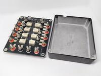
I wanted an aluminum enclosure, both for nice looks and to shield against electrical noise. Hammond 1550MBK was the cheapest suitably sized enclosure I found, and a black PCB could nicely fit in place of its top cover.
For the PCB to work as the cover, all components have to be installed on the bottom side. The LEDs are reverse mount type, which shine through holes in the PCB. Rest of the parts are SMD, and with some careful routing I was able to avoid any traces on the top side.
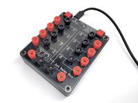
Binding posts were harder to choose. The ones on Digikey were rather expensive, at 2 EUR per each. I needed 20, so this would get expensive. I found some cheap ones (0.5 EUR each) on eBay, but ended up having to drill a wire hole on them myself. I guess you get what you pay for, but a binding post without a cross hole for a wire seems rather useless to me.
I wasn't sure on the best way to mount binding posts to a PCB. Most binding posts are designed for panel mounting, and have an insulating sleeve around the screw. I could make a 6.5 mm hole on the PCB and then solder a separate wire from each post to a pad. But for easier assembly, I decided to remove the insulating sleeve and use direct metal connection between the binding post body and the PCB. This worked well enough, though I did have to add some solder to prevent the connectors from spinning in the hole. Because the screw thread does not go all the way to the bottom, I had to use the plastic washers to space out the nut so that it could be tightened.
Control protocol
Most of my other instruments use SCPI protocol for control. There is a nice library scpi-parser by Jan Breuer that made SCPI implementation easy.
The SCPI standard specifies standard instrument classes, which include "Signal Switchers" category. I implemented the standard command set, and added a few custom commands for convenience.
For USB serial port emulation I used the STM32 Cube libraries, as they were easily available on PlatformIO.
Initially I had trouble getting STM32F042 USB working, until I found out that SYSCFG->CFGR1 has a bit PA11_PA12_RMP that needs to be set to enable the USB pins on 28-pin packages.
After that writing the firmware was very straightforward.
Results

All basic functionality works well. The assembled device has parasitic capacitance of 40 pF from each signal to GND, and 50 milliohm resistance when measured.
I'm not perfectly satisfied with the binding posts, as the threads are a bit rough. For the price they are a good deal.
The USB descriptors used are a bit lazy, as the STM32 library claims the device as self powered. This could be fixed in software, but it's not really important for me.
Design files are available on GitHub.
– Petteri Aimonen on 26.3.2024

