
SMD probe for multimeter
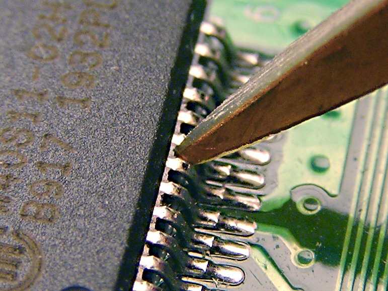
While fixing my laptop, I needed to probe several pins on a surface mounted chip while the system was running. Obviously I didn't want to short-circuit anything by accident.
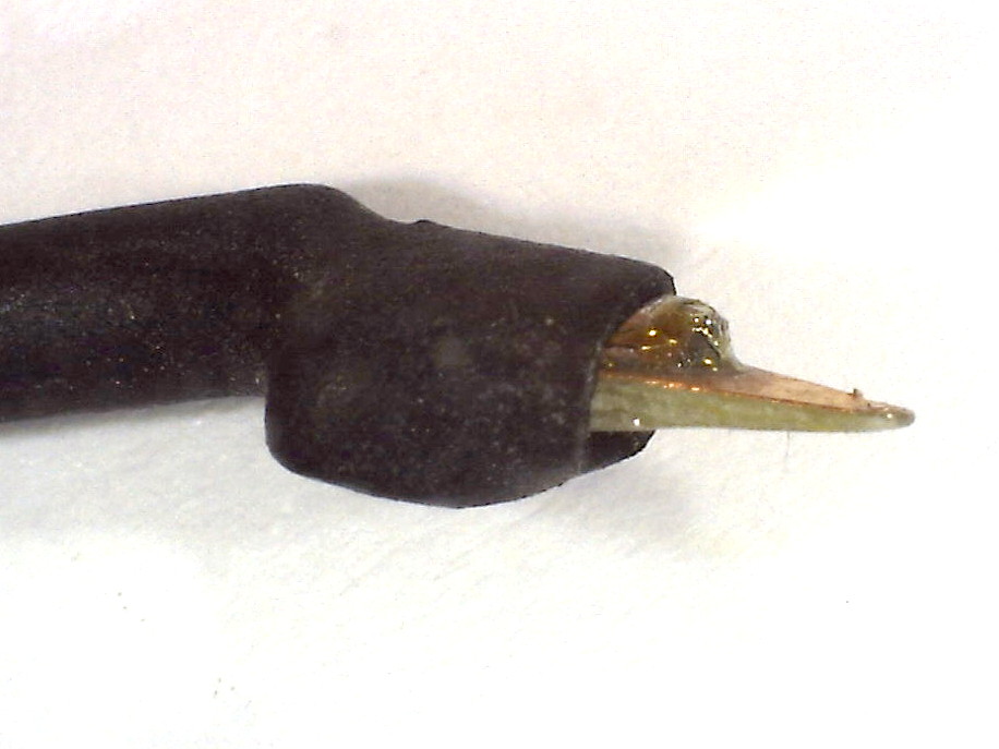
Most SMD probes I found online were either just sharper pins or tweezers for measuring discrete parts. My solution is a bit different: a probe that is conductive only on one side, so that it can be pushed between two IC pins.
Tip construction
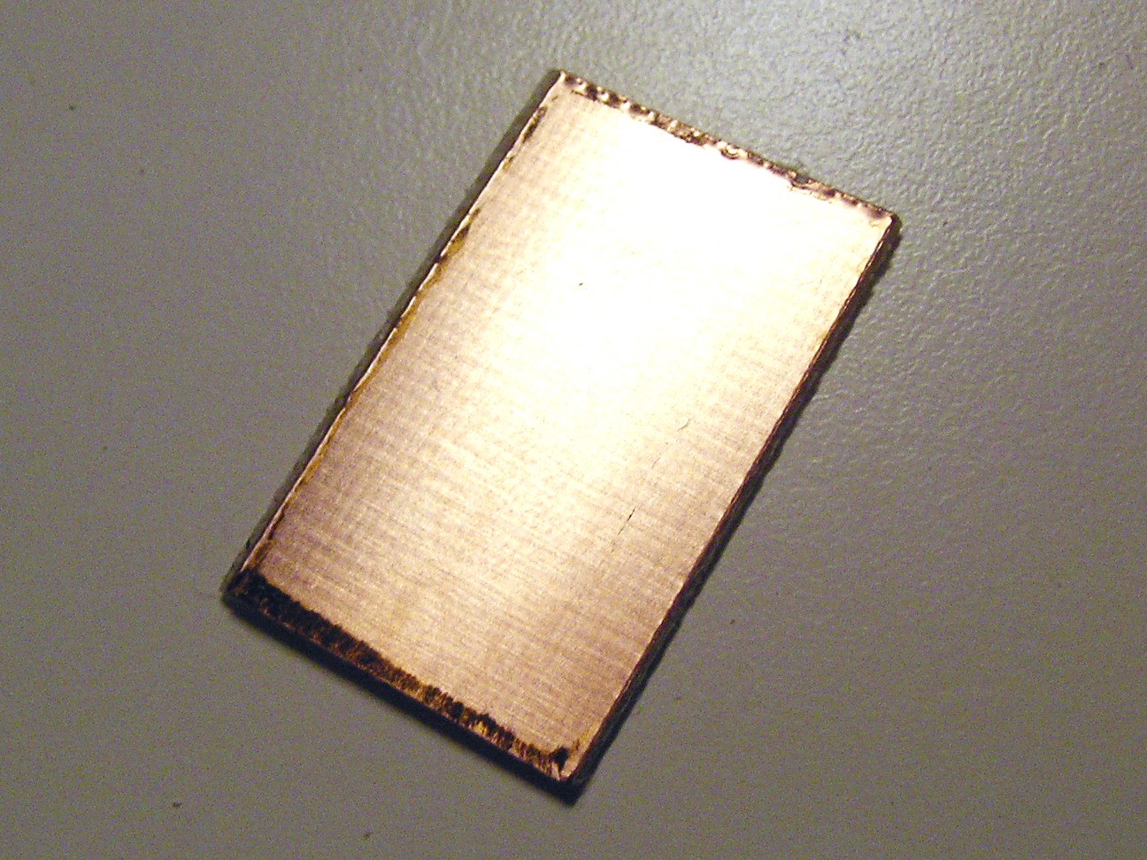

The probe tip can be made from a small piece of fiberglass PCB. Shaping is easily done with a hacksaw and a file.
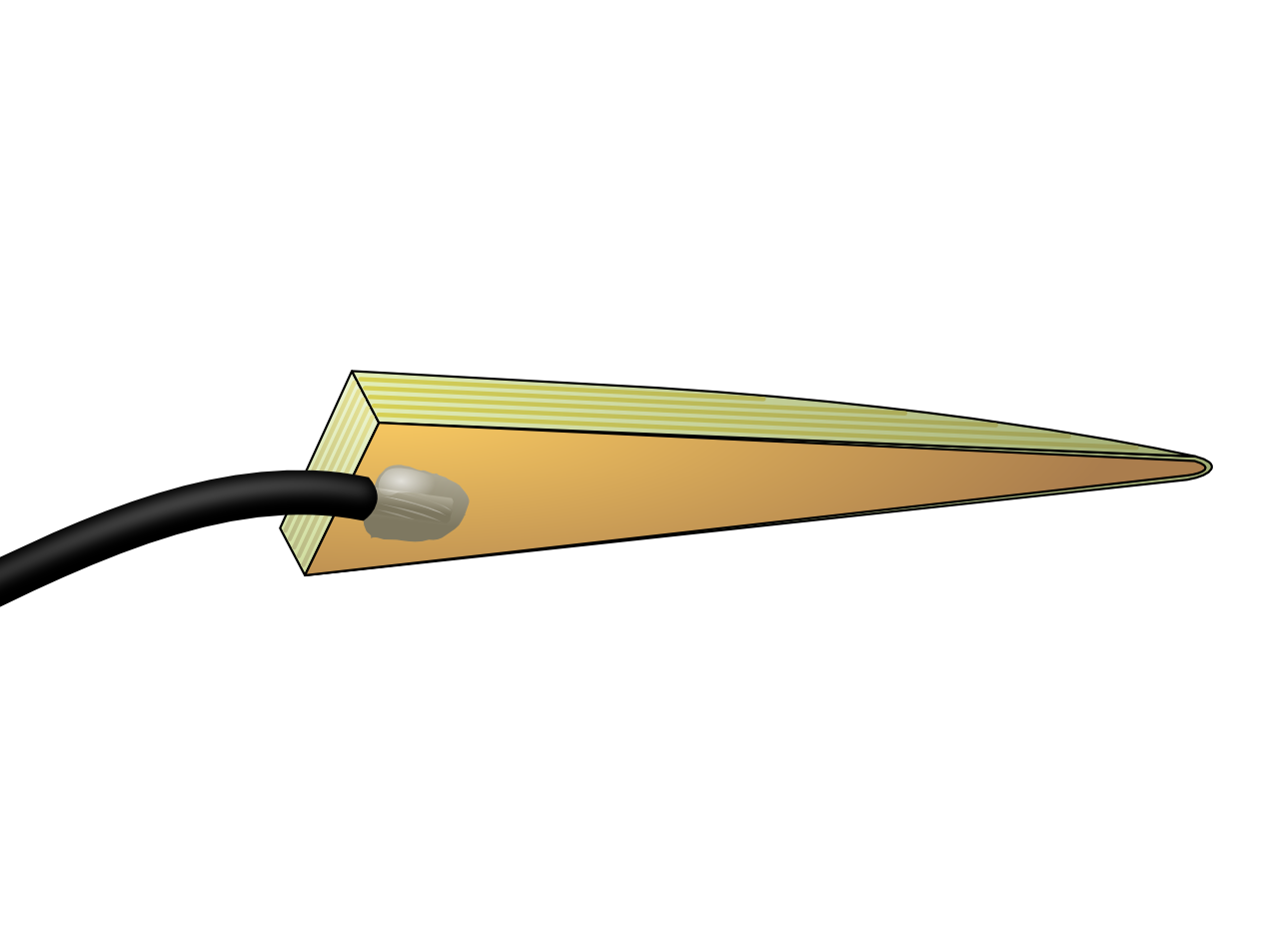
The basic shape is a triangle with a 0.5 mm wide round tip. The board is filed thinner towards the tip, but not too much. When pushed between IC pins it should act like a wedge, pushing securely against each side. At the very tip, a bit of copper is removed around the edges so that the tip won't short-circuit even if inserted at an angle.
My version is a single-wire probe for multimeter, whereas an oscilloscope probe would need a coaxial cable and some trimming to match the impedance.
My ground wire is just a simple crocodile clip connected to some random chasis point, but for an oscilloscope probe you would want a ground point closer to the measurement tip. One option is to have a short wire in between and another probe to push against the IC's ground pin.
Casing
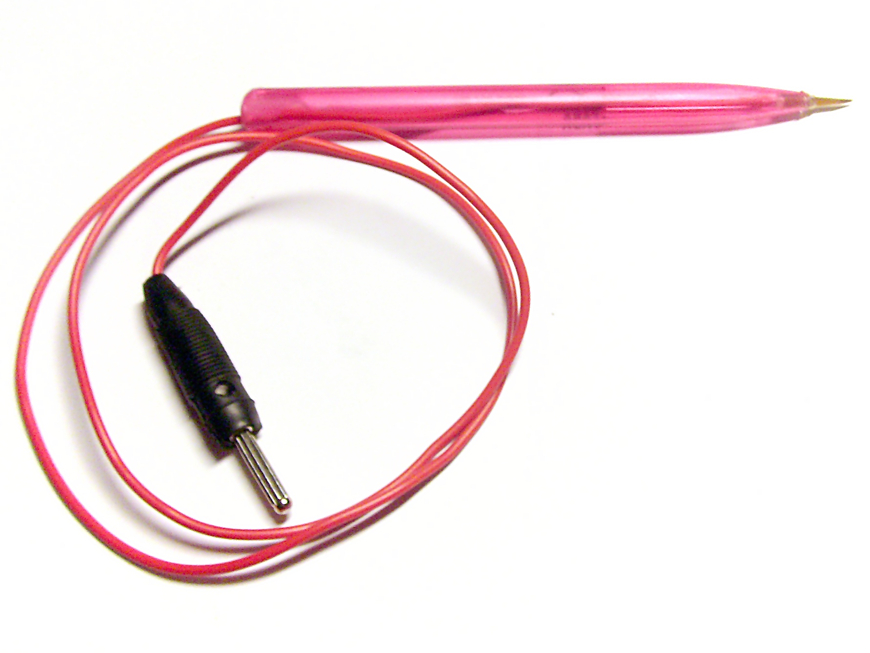
I hotglued the tip to the end of a ball-point pen plastic tube. It may not be the most beautiful case but does the job and is cheap.
With the heavy case the probe will fall off if no-one is holding it. However, if you leave out the case and file a small dent behind the tip, you can just stick it between the pins and it supports its own weight. This could be used in e.g. logic analyzer setups for measuring large number of pins.
Update: Logic analyzer probe for 0.5mm ICs


It is easy to apply the same principle to logic analyzer probes. By making the thickness of the probe suitable, it sticks quite well between 0.5 mm IC pins. Taping the cable to the PCB ensures that it will stay in the place, and you can stack multiple probes close to each other.
In practice it is possible to probe two or three adjancent pins on a 0.5 mm IC using this probe. The copper on the thin tip will eventually wear down, but the material cost comes to just some cents per probe.
– Petteri Aimonen on 25.8.2010