
How to fix a matrix keyboard
My workplace had a Brother label printer with broken keyboard. This isn't an ordinary consumer model; instead, it prints on 30 mm high tape and costs several hundred EUR. Therefore it was actually worth fixing, unlike some cheaper models.
Symptoms
The problem was that one vertical column of keys was not working. The keyboard is a typical scanning matrix of keys, so I suspected a problem with one of the column wires. Dave Dribin has an excellent description about how these keyboards work.
I verified the wiring with a multimeter, but the problem was that one column driver output pin on the microcontroller gave out just 0 volts. Apparently the lower transistor of the CMOS output stage had burned into short-circuit.
The cause of the fault is unknown. As described in the link above, matrix keyboards can short-circuit the column lines if three or more keys are pressed simultaneously. This can damage the driver IC if it uses output buffers that drive both high and low. However, I measured (by connecting a small pull-down resistor) that this particular device was not faulty in this way; instead, it had a 100 kohm pull-up resistor and open-collector output stage.
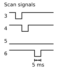
Further analysis with a LogicBridge 136 logic analyzer revealed the waveforms the controller uses to scan the matrix. The idle state of the lines is high (3.3 V) and each signal switches low for 5 ms in turn. The controller seems to automatically detect stuck lines, because the permanently-low column signal did not cause any keypresses.
Emulating the scan signal
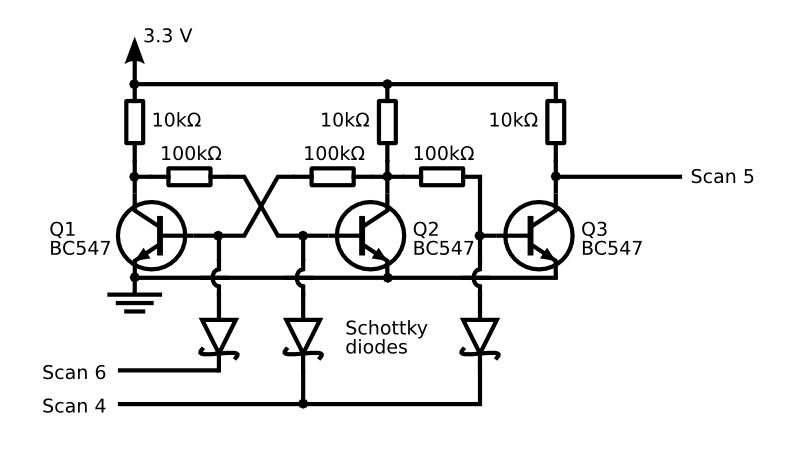 I chose to implement the logic with plain old transistors.
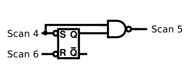
The fix is to generate the missing scan signal from the preceding and following signals. This would be a simple job for a microcontroller, but the waveforms allowed for even simpler solution using an RS flip flop.
Both high-level logic gate schematic and low-level implementation with discrete transistors are shown. The scan signal 4 is connected to set, so it activates the flip flop. The following scan signal 6 resets the gate to return to idle state.
Because this RS flip flop is not clocked, it activates immediately when set goes low, and the output would therefore overlap with the previous scan signal. To fix this, the flip flop output is fed to a NAND gate with the scan signal 4 to produce the output signal scan 5.
How to apply
I expect that most matrix keyboards could be fixed in this way, provided that the scanning signals follow each other immediately. More complex waveforms would require a microcontroller, and a logic analyzer or oscilloscope is a must to find out the proper timings.
Note that there is not much that can be done if an input pin is fried. But they should not be as prone to damage from short-circuits anyway. If you have success with this method, please tell in the comments!
– Petteri Aimonen on 24.7.2010