Repairing stripped internal gear

After a decade of hard use, a plastic gear in my Black & Decker Gyro Driver screwdriver gave up. I really like the small form factor and precise control, but the model is no longer manufactured. Therefore I set out to repair the one I have.
What is a gyro driver?
Gyroscopic screwdrivers only have a single push button. Rotation direction and torque is controlled by turning it. Turn it clockwise and it spins that way, turn a bit further and it spins faster.
I find this works great in practice and makes it easy to control the torque precisely. The Black & Decker one also has a clutch on the output, making it possible to apply even more torque by hand for final tightening.
There is a good teardown of the device on YouTube channel Daft Old Man.
Stripped gear
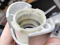
The motor has two sets of planetary reduction gears, which share a common ring gear made in plastic. The high torque set had stripped the teeth off its section in the ring gear.
The low torque set uses plastic gears as the planets, but the sun gear on the motor is made of metal. In the high torque set both sun gear and planets are made of metal, but the ring gear is plastic. It seems reasonable to use metal for a more durable replacement.
However, I don't have machinery needed to directly manufacture inner gears in any material.
Repair plan
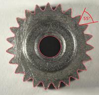
I started by measuring the gear geometry. I did this by taking a closeup photo and comparing against gear outline generated in Inkscape.
- Pitch: 1.5 mm
- Pressure angle: 30°
- Planet gear teeth count: 23
- Ring gear teeth count: 56
The gears appear to have involute gear profile, but the pressure angle is uncommonly large at 30°. I think it may be selected to make the plastic teeth more durable. It makes my task easier, as the teeth are very close to being 55° triangles.
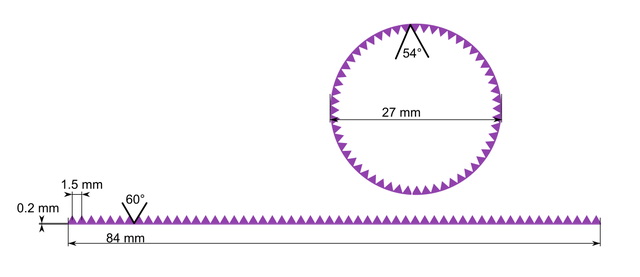
I figured I could use a 60° carbide V-bit to make grooves in a steel plate, which would then form triangular teeth between the grooves. The sheet metal could then be rolled up into a circle to make the gear. Bending the sheet reduces the angle between adjancent teeth by about 6°, getting it very close to the 55° target. The old plastic teeth will be milled away, and the replacement glued in place.
Results
Cutting the gear sheet was easy on Hacklab Jyväskylä's CNC. There were some burrs that needed manual removal with a file and sandpaper. I left about 0.2 mm thick spine behind the teeth.
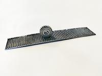
I rolled up the ring using a round pipe. The last teeth on each side needed to be separately bent using pliers. The clutch ring was useful for alignment while soldering the ring together. After soldering I filed it smooth.
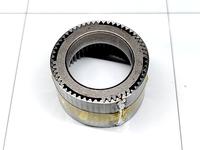
Positioning the plastic housing for accurately milling out the old teeth was more difficult. I clamped the nose part on a vice, to avoid deforming the part with the gears. I made initial alignment using camera on the CNC. To get more accurate centering, I made first cuts so that they just barely touch the gears, and adjusted on-the-fly X/Y offsets until milling sounds were equal on all sides.
On first fitting the ring didn't quite go in, so I milled 0.1 mm further in radius. In retrospect this was unnecessary and the initially calculated fit would have been more accurate. I had to insert a few shims during glueup to make the ring stay centered.
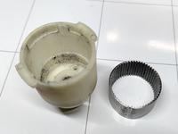
After gluing the ring in place with some epoxy there was only assembly remaining. I applied new grease to the gears and ran the motor for a while. Everything ran smoothly, though the seam in the ring makes a small click every time the metal gears pass it.
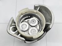
Fully assembled, I tested the driver to the limits of its motor torque and the glue held up fine. Hopefully this fix will give it another decade of operation. I may have to replace the battery at some point, but it is a standard 18650 cell so that should be an easy task.
– Petteri Aimonen on 12.8.2024
