
EMF detecting wand
My coworker has this nifty tool that he uses to check standby modes on various devices. It works by detecting electro-magnetic fields and converting that into sound. Seeing his stripboard design that he has carried with him for 10 years, I just had to clone it.
The tool has a coil on one end, and speaker on the other end. His version runs from a 9 volt battery and the coil is made around the tube of an old pen. A small coil with high amount of turns allows sensitive detection of currents in a relatively small area, so that you can monitor e.g. a switcher separate from the MCU.
It is possible to get similar results by using a microphone. But I had not seen anyone using this technique for debugging embedded devices before.
Figuring out the schematic
Only problem was that there never was any drawn schematics for the device, and the prototype had been covered in hotglue after (I assume) repeated repairs during its years of operation. As such parts of the circuit were unknown, but enough remained to figure it out.
My initial capture of the schematic had some missing bias resistors. After an unsuccessful quest for information on Stack Exchange, I found out the required combination by trial and error. Later I found out from the same coworker that the preamplifier design is originally from an intercom design, where a speaker is used as a microphone. Seems that it is relatively unknown outside this specific application, even though it could be useful for many kinds of low-impedance sensors.
The schematic in itself is quite simple. Two NPN transistors form the preamplifier stage, which is AC-coupled to an audio amplifier chip (originally LM386). One trick is separating the power supplies of the input stage and power stage using RC filters, as otherwise feedback loops can easily occur. The voltages sensed on the input stage are on microvolt level, so the preamplifier is quite sensitive to noise — as it should be, considering what it is trying to measure is essentially electromagnetic noise.
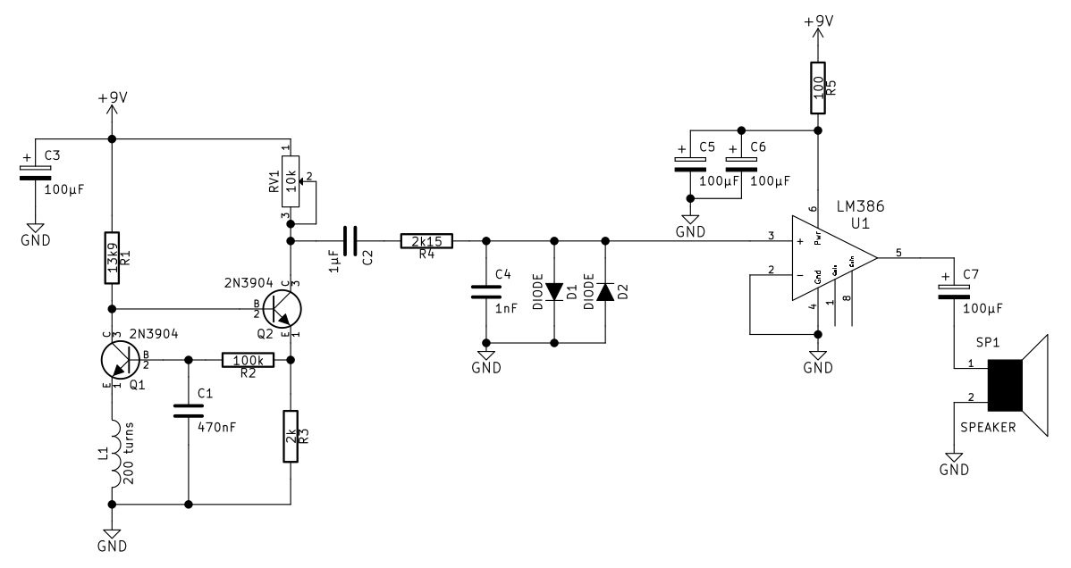 Original schematic of my coworker's version.
The circuit does not have any downconversion, so you can only hear audio frequency noise. What it detects is usually the fluctuations in power draw of a circuit - things like waking up from power save, writing to memory or transmitting over radio.
The probe is simply a coil of copper wire. The size and amount of turns in the coil affects the sensitivity, as does air vs. ferrite core.
Modifications
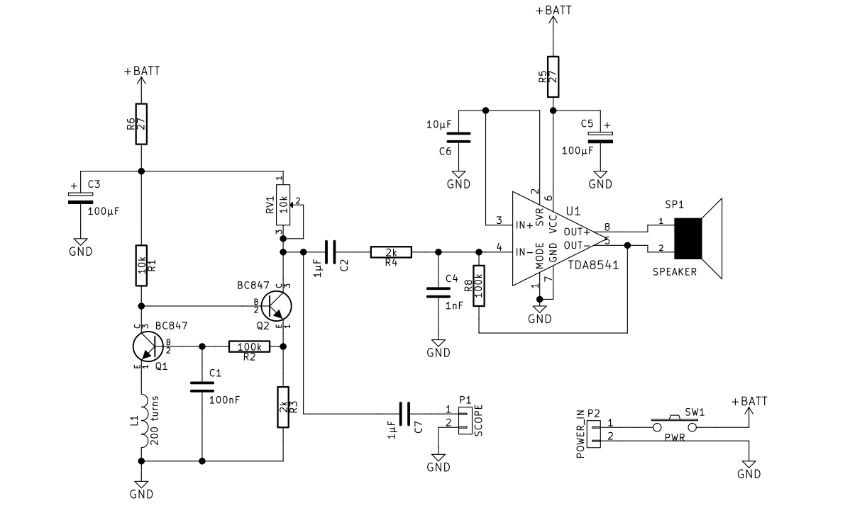 Updated schematic.
With the original schematic figured out, I made a few modifications. Conversion from LM386 (single-sided speaker drive) to TDA8541 (double-sided drive) amplifier chip allows operation with a lower supply voltage. I also added an output for connecting a scope, for closer studying of the captured signals.
Implementation


The PCB was designed in Kicad and milled out on CNC3020. It turned out pretty good, considering it was my first milled PCB.
I designed a case in Solvespace and 3D-printed it out of black ABS. Three LR44 button cells supply the 4.5V operating voltage, and the probe end can be swapped to alter sensitivity.
The probes connect with a four-pin connector, while only two pins are actually in use. I initially planned adding a LED, but the probes I have made so far make no use of the two LED pins.
If your browser does not support WebM for video, you can either watch on YouTube or download the video.
End result

I'm quite satisfied with the end result. It is especially useful for detecting operating modes of devices without opening them up. The range and recognition abilities of the human ear limit the ability to make exact measurements, though. One can easily imagine a more advanced version, with fourier transform for spectral display.
You can download KiCAD files for the PCB and SolveSpace files for the case.
– Petteri Aimonen on 3.8.2015