
Improving the digital bandwidth
I have mentioned before that the protection diode D5 on the DSO Quad's digital channels is poorly chosen. It has 5 V threshold voltage, and also awfully high capacitance. The capacitance ruins the digital bandwidth, and the high threshold voltage means that it doesn't really protect much anything.
Fortunately, there is a simple fix: just remove that diode. In this post, I'll show how to open the DSO Quad and remove the diode. I will also study how large voltages are safe to connect to the digital channels.
Doing the hack
Opening the device
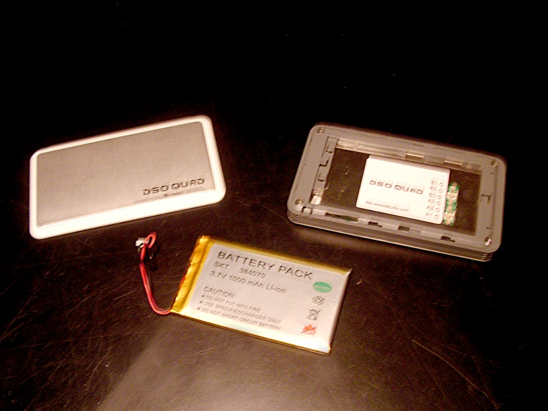 Battery removed
The DSO Quad is very easy to open. It is held together by just four Philips #1 screws and some clips.
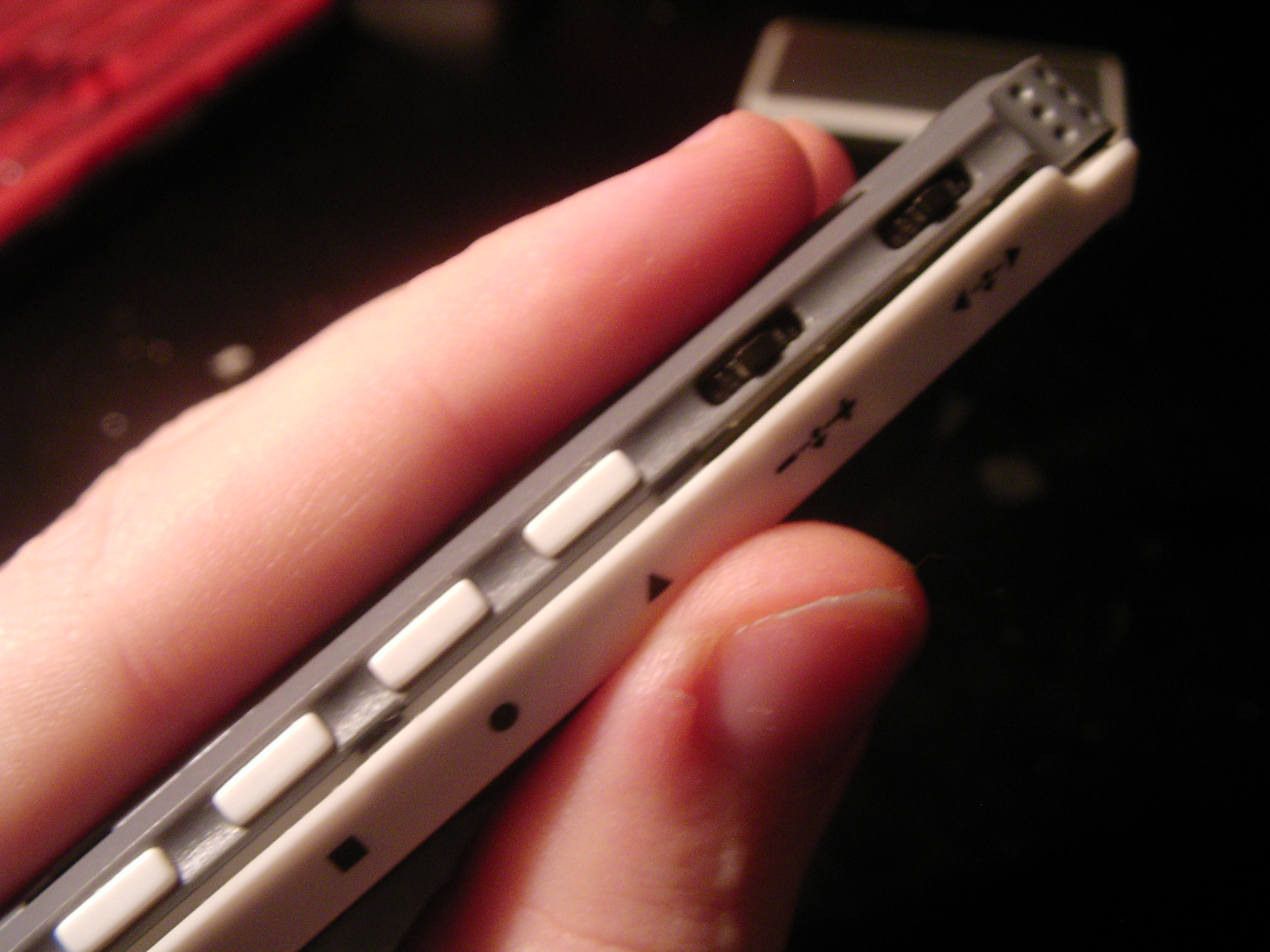
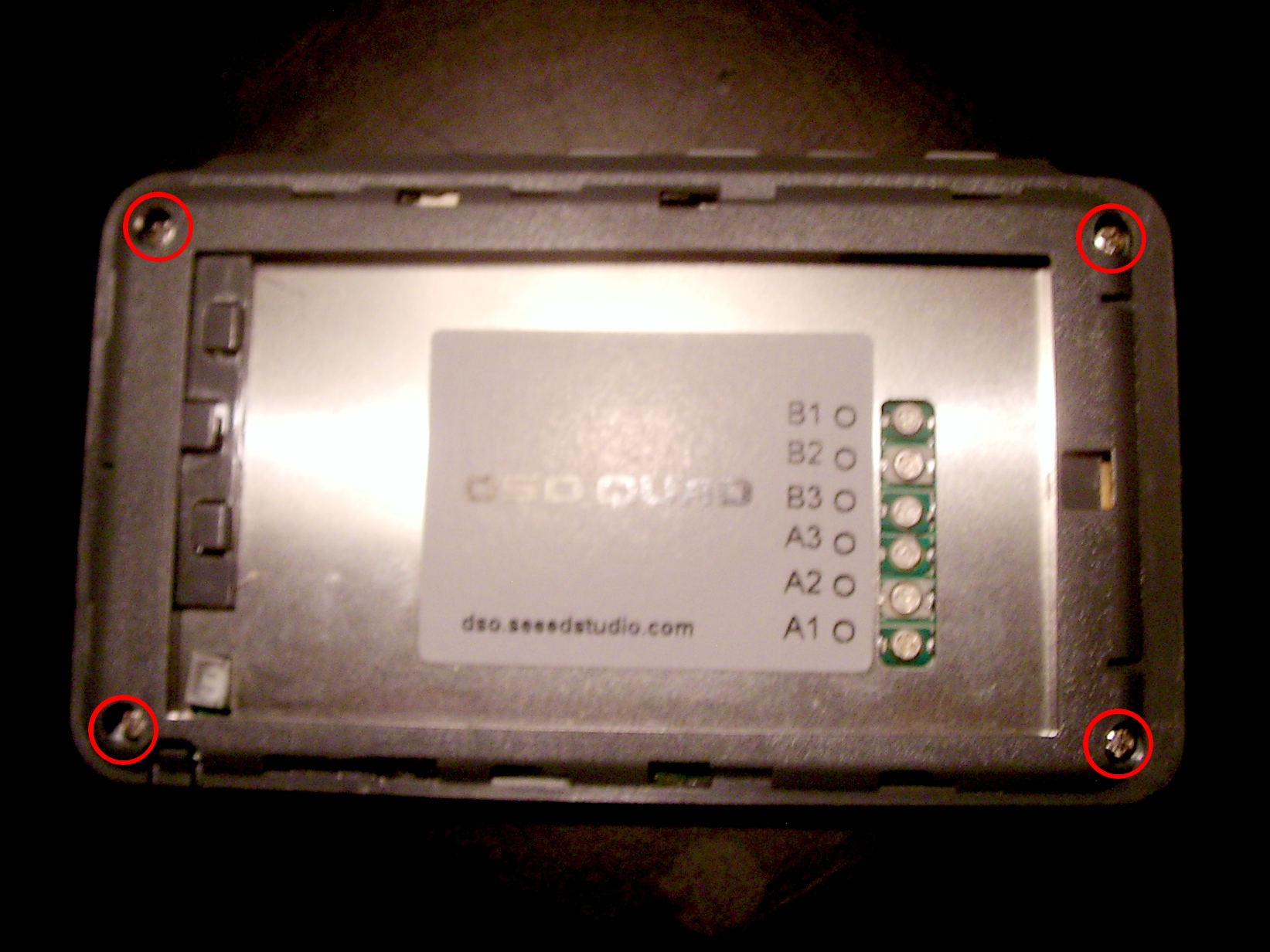 Screw locations
Start by sliding open the back cover and detaching the battery. Unscrew the four screws in the corners.
 Removing the front panel
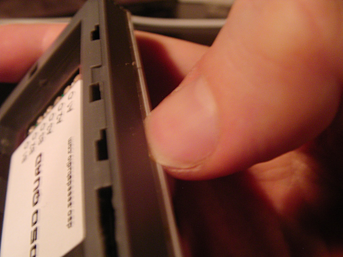
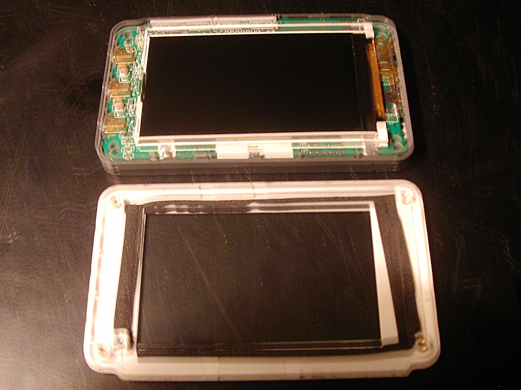 Case opened
Remove front panel by sliding your finger nail under the bezel. It should come off quite easily.
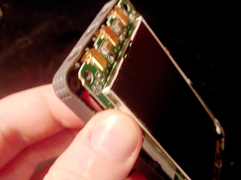 Removing PCB
Finally, remove the PCB by gently pushing it from underneath. Don't use too much force to avoid damaging the buttons.
Removing the diode
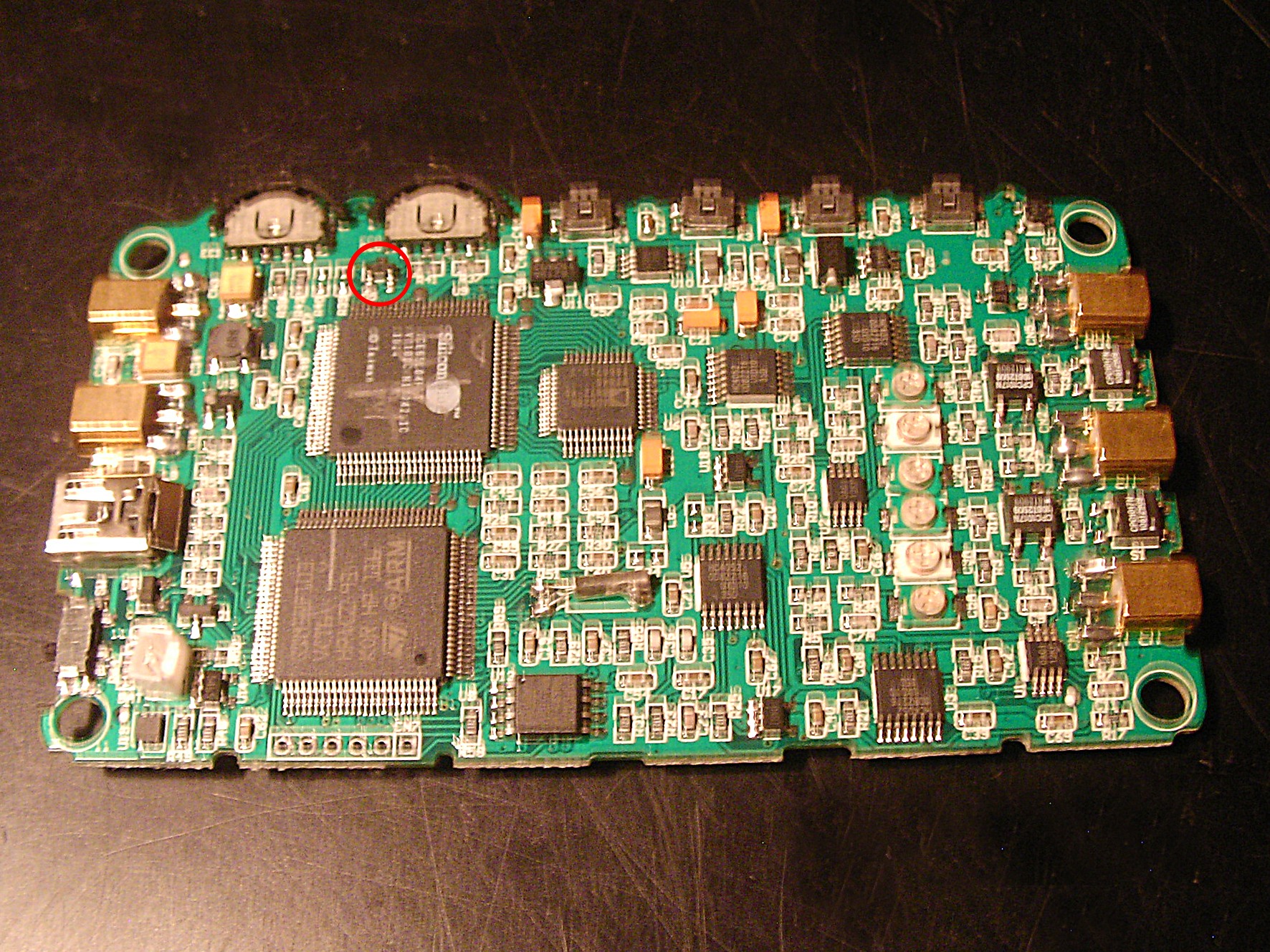 Diode location
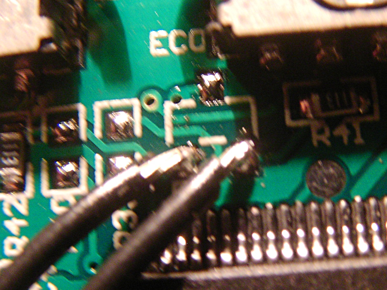
Locate the diode labeled "D5" near the scroller wheels.
 Soldering
Use some sharp tool to carefully lift the diode off the PCB while heating the connections with a soldering iron.
Reassembling the device
 Putting the front panel back
Replace the PCB in the frame. Make sure that the plastic button caps are still in place. Note that the power switch has to be in correct position to align with the knob.
This is a good opportunity to wipe clean the screen. Any fingerprints will remain under the front panel, which just snaps into place.
Screw back the 4 screws. Reattach battery, close the back cover and you are done.
How safe is this?
You may be a bit worried about removing the protection diode. However, consider the following schematic, which represents one of the DSO Quad's digital channels.
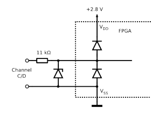
The external protection diode will not do anything until the voltage on the pin rises to 5V. Because the FPGA (like most CMOS devices) also contains internal protection diodes, the voltage will never rise this high unless the device is already broken.
 Test wires
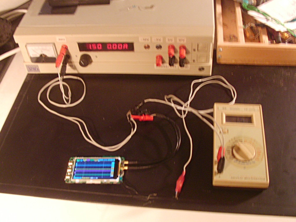 Test setup
To verify this, I soldered wires to the (now free) diode pads. These are in parallel with the FPGA pins, so I'm able to compare the voltage with the FPGA datasheet absolute maximum ratings of -0.5 to 3.6V.
I tested voltages -7 V to +24 V, on channels C and D. Both channels behaved identically:
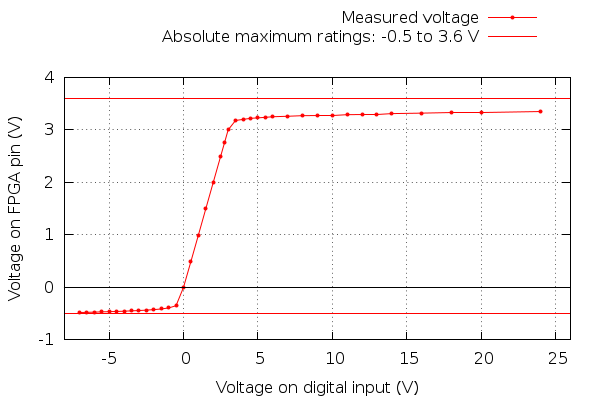
Based on this, I can say that -7 V to +24 V did not damage my device, and does not exceed the maximum ratings. Positive voltages have much more margin. Because digital inputs report anything less than about 1 V as 0, negative voltages would not be very useful anyway. One situation where they could matter would be measuring RS232 signals.
If one wanted to be absolutely safe, substituting BAT54A as D5 could be a good solution. It would handle the negative voltage side, and has a low capacitance.
What is the bandwidth?
The digital inputs on the FPGA have a capacitance of 6 pF. This gives a -3 dB bandwidth of 2.4 MHz, but for digital signals I would say it is usable up to about 10 MHz. Probably even 12 Mbps USB 1.1 could be measured.
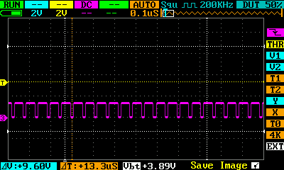
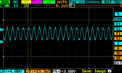
For reference, here is a 18 MHz 5 Vp-p square wave, first on a digital channel and then on analog one for comparison:
– Petteri Aimonen on 4.11.2012